
Discerning customers who require broadband communications at sea are completely dependent on satellite communications as it provides the only bearer available anywhere, anytime.

Many would not bear the expense unless the satellite link were resilient and high availability. Redundancy can be improved by using multiple satellite systems, and multiple transmitters, since high power solid-state power amplifiers (SSPAs) are usually the most failure prone component in the link.

Frequency stealth can improve resilience by switching or spreading either the modem output frequency or the RF frequency. Changing to a lower frequency band can also protect against weather effects that cause attenuation of the satellite link at higher frequencies such as Ka-band, in spite of their superior bandwidth and capacity.
More specifically, the shipboard terminal determines one critical part of the reliability equation. Communications availability can be improved when the link budget is optimized by using the highest power transmitters possible, the most sensitive receivers, and steered antennas to maintain maximum antenna gain and achieve the best lock on the satellite.
Terminals such as the EM Solutions maritime Cobra terminal are in demand by the world’s greatest navies as they offer all of these features. With multiple band resiliency in a single package, the Cobra covers both commercial and military Ka-bands, as well as X-band simultaneously [1,2].
The new Cobra Fleet terminal uses a 2 meter antenna and will cover X-band and the entire available Ka-band spectrum on any satellite system.
Even given these features, time-on-satellite is a big contributor to the availability equation: minimizing the time for an on-the-move terminal to acquire or reacquire the satellite is crucial, as is maintaining the link under violent motion conditions. That is achieved in the Cobra through its sophisticated monopulse pointing and tracking system.
However, what if the line of sight to the desired satellite is blocked, say, by the ship’s infrastructure due to the vessel’s temporary orientation? The solution can be seen on premium ships that have two terminals (or ‘above deck equipment’, ADE) mounted on opposite sides of the bridge.
Most simply, traffic can be switched at the data layer, using IP addressing, from the blocked terminal to the other terminal with the best ‘view.’ However, while this might be acceptable for commercial traffic, such a data layer approach is too intrusive for government or defence users. WGS, Inmarsat GX and other Military and Commercial Satellites
Rather than at the IP layer, the Cobra’s new Antenna Diversity System (ADS) achieves this switching at the physical layer, so that encryption and security wrapping around the data is preserved intact. The ADS mediates between two antennas and one or more modems by directly switching the modem traffic to the desired terminal.
Figure 1 illustrates the concept. Also, consider the features a government or defence user might require, through the lens of maximum resilience and flexibility:
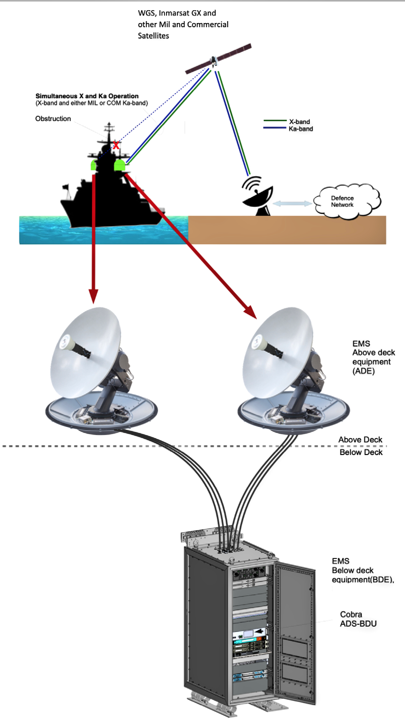 Figure 1: Basic components of dual ADE system using the Cobra Antenna Diversity System.
• Operating with a modem bank that supports multiple frequency bands and satellites, for instance the WGS satellite system (X-/Ka-), Inmarsat GX (Ka- commercial), and other Military or Commercial satellite networks
• Operating each ADE from either individual (separate) modem banks or a common modem bank
• Switching both X- and Ka-band traffic to one or both ADEs
• Supporting single look operation (both ADEs to the same satellite) or dual look operation (both ADEs to operation (both ADEs to independent satellites)
The ADS (Figure 2,) is able to support all possible combinations of the above, but shields its complexity through a simple interface to the user. The ADS is able to support all of these through its proprietary, in-built IF switch matrix that switches the output signal of up to eight separate modems to one or both ADEs, and multiplexes the resultant signal, for both outbound and return traffic, onto a single cable pair for each ADE.
As illustrated in Figure 3, an IF-pair switching matrix allows any modem to be connected to any RF path of the two ADEs. There are four RF paths (paired for transmit and receive) available:
• ADE 1 Ka-band
• ADE 1 X-band
• ADE 2 Ka-band
• ADE 2 X-band
Each RF path can be connected to a single modem, or no modem, depending upon configuration. The four paths can be used simultaneously, depending on satellite features and satellite resource allocation.
Figure 4 shows the ADS from the rear, with its top panel removed. Supporting multiple modems, some with different interfaces, as well as multiple RF outputs and management interfaces, means that the ADS also serves as a convenient single ‘wiring’ hub.
Example Usage Scenarios
On the following feature page, various usage scenarios for a defence customer are based on operation across two military satellites (for example, WGS and Optus C-1) and one commercial satellite (Inmarsat GX). Other satellite systems can be added into the ADS operation as required.
Single Satellite Look Handover mode (obstruction mitigation)
In this mode, the BDU configures both ADEs to track the same satellite, but only one ADE at a time is allowed to transmit to the satellite. The BDU selects which ADE to connect to the active modem(s) to avoid obstruction outages. This is illustrated in Figure 5 and Figure 6, futher below.

Figure 2: The Antenna Diversity System ADS is a rack-mounted unit that can mediate between above deck antennas and multiple modems operating at multiple frequencies.
The target satellite can, for example, be from the WGS or other MILSATCOM network, or from the Inmarsat GX network. When operating on a Military satellite with multiband capability, the active ADE can simultaneously support both an X-band and a Ka-band carrier. As the ship maneuvers, the below deck unit (BDU) monitors how close each ADE is to an obstruction. The configured wooded arcs and exclusion zones are used as the definition of obstruction zone. The BDU will switch between ADEs if the active ADE becomes too close to an obstruction and the other ADE is not obstructed. The threshold for switching is user configurable.
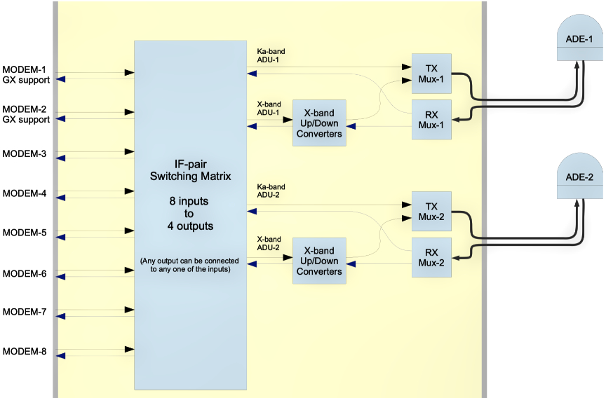
Figure 3 shows the simplified functional block diagram of the modem
selection function.
To minimize outages during ADE switch over, the BDU supports the tactical modem’s “Antenna Handover” features (if available) and also complies with the Inmarsat GX antenna handover process.
Independent ADEs Mode
In this mode, the system configures the ADEs to operate independently. Each ADE can either track the same satellite, or different satellites (when supported by the network). This is illustrated in Figure 7 and Figure 8, furhter down.
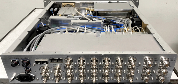
Figure 4: The Cobra Antenna Diversity System viewed from the rear, showing the switch matrices internally and connectors for multiple modem connections on the rear panel.
Providing resilient, high availability satellite communications is the job of both the satellite network operator and the ground terminal provider.
Today, terminals such as the Cobra or Fleet that switch automatically between satellites and frequency bands can provide redundancy in the space segment. Redundancy on the ground can be provided, as well, with dual terminals and the flexibility to configure them in such a way that traffic flow continues uninterrupted when one terminal is blocked or fails.
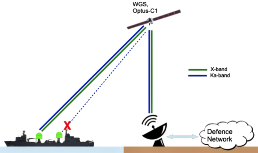 Figure 5: Dual antennas in handover mode operating on a military satellite.
 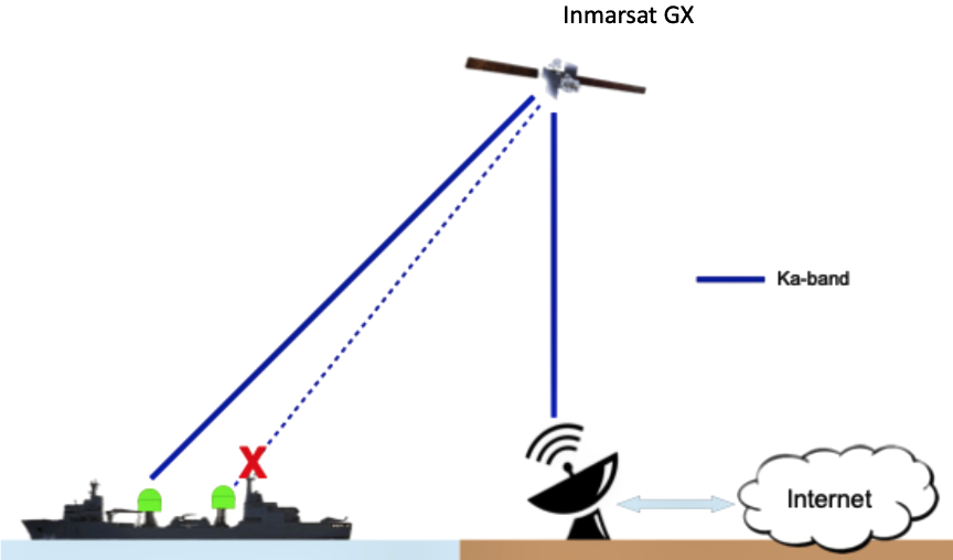 Figure 6: Dual antennas in handover mode operating on Inmarsat GX.
X
XXX
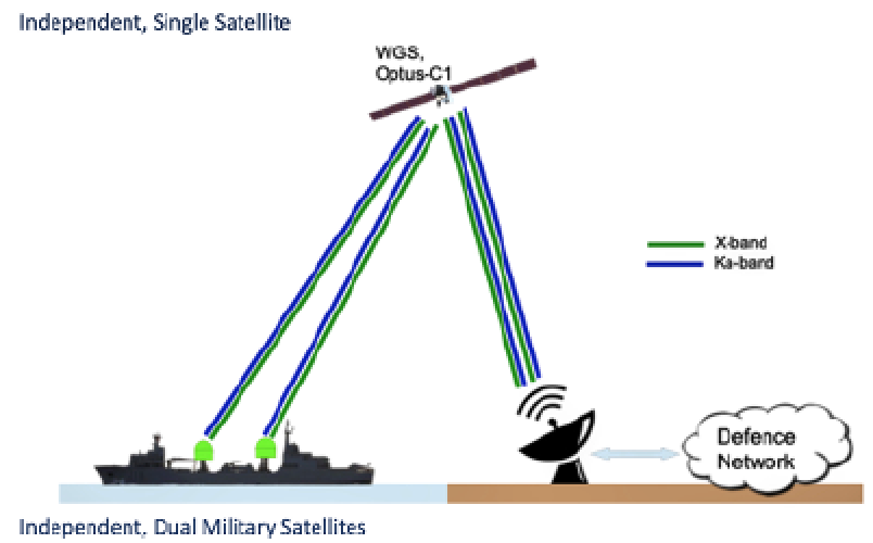 Figure 7: Independent ADEs operating on single satellite.
 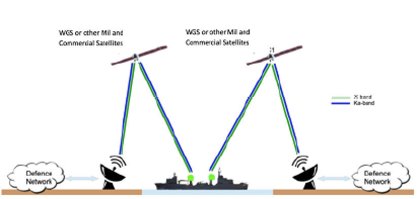 Figure 8: Independent ADEs operating on separate satellites.
Systems such as EM Solutions’ Antenna Diversity System provide such flexibility, and strengthen the resilience required of high availability broadband satellite communications.
References
[1] “Robust Satellite Tracking On The Move,” R. J. Gilmore, MilsatMagazine, March 2017.
[2] “Equipping Defence Forces for Assured On-the-Move Communications”, R. J. Gilmore, MilsatMagazine, October 2016.
Author Dr. Rowan Gilmore joined the EM Solutions Board of Directors in 2007 and became Chief Executive Officer in October 2011. His role as CEO is to lead EM Solutions to achieve its vision to inspire customers globally, as a trusted technology developer of the most innovative microwave and on-the- move radio and satellite products that help to deliver high speed telecommunications anywhere in the world.


His previous experience includes Vice President, Engineering at Compact Software, where he introduced the world’s first harmonic balance nonlinear circuit simulator, and as Vice President, Network Services Europe for SITA-Equant, the global airline IT company, now part of France Telecom’s Orange network. Most recently he was CEO of the Australian Institute for Commercialization, where he helped numerous start-up companies and worked to accelerate technology transfer between research institutions and industry.
Rowan obtained his D.Sc. in Electrical Engineering from Washington University in St Louis. He is an adjunct professor of Electrical Engineering at the University of Queensland, and was elected a Fellow of the Academy of Technological Scientists and Engineers in 2009. Rowan will be known to many in the microwave engineering community who have attended his short courses on microwave circuit design and RF wireless systems offered by Besser Associates and CEI Europe since 1990.