
Just as today’s mobile phone user expects to roam across different countries and networks with a common handset, so, too, does the modern Defense Force user demand true broadband services across a range of different satellite options—without having to use multiple SATCOM terminals or experience an outage while swapping different RF kits.
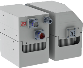
EM Solutions Diamond Series Model 360 Ka-Multiband nanoBUC™.
EM Solutions has such an On-The-Move (OTM) , maritime, tri-band terminal currently under development. This new terminal will allow seamless access to SATCOM services over a range of satellites and will also counter troubling effects, such as geographical location or rain fade.
Although one or two simultaneous Comms-On-The-Move (COTM) terminals in X- and Ka-band already exist in the market place, the new EM Solutions product offers some key differences.
Ka-band OTM operation on the WGS satellite constellation imposes stringent constraints on pointing-error control. These constraints are due to a combination of regulatory, antenna pattern and link-budget considerations that are required to efficiently use the available bandwidth on these satellites.
For example, during transmission, it is important that the beam is pointed directly at the desired satellite, rather than off-center, where it may leak to another satellite or reduce the desired signal level below its detectable threshold. While the actual pointing-error requirement for a Satellite-On-The-Move (SOTM) terminal will depend on a number of parameters, such is likely to be on the order of a few tenths of a degree.
This degree of pointing accuracy is quite difficult to achieve with an open-loop tracking system that relies solely on inertial measurement systems to steer the antenna. Furthermore, inertial measurement systems rely on GPS measurements made at a frequency that cannot account for beam refraction through the radome.
This means that such systems are susceptible to radome variations and large offset errors that depend on the angle of incidence and the RF frequency of the measurement signal. EM Solutions has adopted a closed-loop tracking system that directly measures the pointing-error using the satellite signal itself for all three bands of the Tri-band terminal.
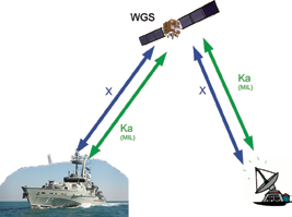
Figure 1. The terminal allows simultaneous X- and Ka- communications on WGS.
Simultaneous X-/Ka-Bands
The EM Solutions Tri-band terminal offers three bands: military X-band, military Ka-band and commercial Ka-band. The same feed and antenna supports all three bands without the need to swap any RF equipment.
The Ka-band Diamond Series BUC also allows the user to select which bands inside the 3GHz spectrum—from 28GHz to 31GHz—are to be electronically switched.
Simultaneous X- and military Ka- operation can occur on military satellites, such as WGS or Optus C1. However, the terminal also supports simultaneous operation on X-band and commercial Ka-band, if a satellite that supports these two bands is available, as shown in Figure 1.
Polarization switching between LHCP and RHCP is handled by electronically switching the Tx and Rx for both bands.
If the terminal experiences congestion, rain fade, or unfavorable atmospherics on the Ka-band military payload, the terminal will continue to use the X-band payload, as shown in Figure 2 on the next page.
The Tri-band terminal will automatically close-loop track the satellite beacon with either the X- or Ka-band RF receiver, depending on the
beacon strength.
Monopulse Tracking On Both X- + Ka-band
The Tri-band terminal feed design supports X-band and both military and commercial Ka-bands and also uses monopulse tracking in both X-band and Ka-band. This is a complicated achievement, as the Ka-band horn must be placed inside the X-band horn without affecting the performance of one interacting with the other.
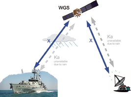
Figure 2. X-band operation can continue during Ka- outages due to weather. Below deck equipment provides detection of Ka- outage and traffic prioritization and routing.
This means that the Tri-band terminal can operate in Ka-band (commercial or military) mode only and track a Ka-band only satellite, and similarly, operate in X-band mode only and track an X-band only satellite. The X-band and Ka-band tracking are independent of each other.
The monopulse tracking in both bands reduces the power consumption of the terminal, as there is no need to mechanically scan the antenna
to perform conical scans or step track pointing, and also increases tracking performance.
When tracking a satellite with both X- and Ka-band transponders, the terminal can switch tracking between the X- and Ka- beacons without introducing significant pointing errors. This allows the terminal to switch from X- to Ka- tracking at the end of a Ka- outage (e.g. due to weather) without disturbing X-band communications.
The Ka-band tracking is expected to give the best tracking performance in clear sky conditions. However, the terminal will continuously monitor the signal quality of both X- and Ka- beacons and will automatically use the band that provides the optimal pointing performance.
The terminal can track common satellite beacons such as CW signals and lightly modulated telemetry signals that have a prominent CW component (e.g., WGS beacons). Also possible is the ability to track data carriers (e.g., DVB-S2, QPSK) with the antenna control unit’s (ACU’s) signal processing capability.
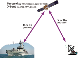
Figure 3. Operation on a single military X- or Ka-band.
The Tri-band terminal has three main tracking modes:
• Search
• Track
• Gyro hold
Search Mode
In search mode, the terminal scans a region of the sky looking for a satellite beacon to use for tracking. Search is an open loop pointing mode. The terminal combines information from the GPS location and AHRS (Attitude and Heading Reference System) with knowledge of the satellite’s longitude to determine where to point the antenna with respect to the vessel.
With this information, the terminal calculates the pointing direction, relative to the vessel, at which the satellite should be found. A small patch of sky is then scanned around this pointing direction. At all times, the Tx is inhibited when the terminal is in search mode. Once the satellite beacon is located, the terminal switches to tracking mode.
Track Mode
In track mode, the terminal uses monopulse to estimate the current pointing error, which is used to steer the antenna back toward the actual satellite position. “Track” is a closed-loop tracking mode. The Tx is not inhibited when the terminal is in track mode and the estimated pointing error falls within the regulatory and user configured thresholds. The monopulse tracking approach uses a signal from the satellite, normally the beacon. If the beacon is suddenly lost (e.g., due to an obstruction), the terminal will enter gyro hold mode.
Gyro Hold Mode
In gyro hold mode, the terminal uses feedback from embedded gyros to keep the antenna pointed toward the satellite. This enables faster reacquisition once the obstruction has been cleared and the satellite beacon is detected again.
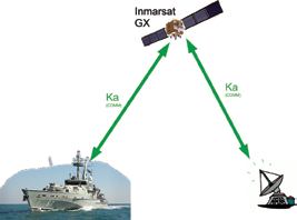
Figure 4. Operation on commercial Ka band satellites including Inmarsat GX. Commercial satellites with military Ka-band transponders are also supported.
After being in gyro hold for a certain length of time, the BUCs are automatically muted to prevent interference with other satellites due to accumulated pointing error caused by gyro drift. If the satellite beacon is successfully found, the terminal will return almost instantly to track mode. If the satellite beacon is not found within a certain period, the terminal will return to search mode.
Three Axis Balanced Terminal
One of the most important features of the EM Solutions Tri-band terminal is the use of a third axis, which is referred to as cross-elevation (this is in addition to the traditional elevation and azimuth axes). The concept of “letting the antenna remain still” has been used throughout the design of the system and this can be seen by the use of contactless, low friction, direct drive motors rather than having gearboxes or drive belts.
Having this balanced axis is important as the antenna’s inertia keeps the antenna still, despite motion of the vehicle underneath it. Thus, the antenna naturally tends to maintain pointing even while on a moving vehicle.
This is not the case for a two-axis (azimuth over elevation) system. Two-axis systems have difficulty tracking satellites directly above the antenna (i.e., perpendicular to the base of the antenna). This problem is often called the “key-hole effect”.
The keyhole effect requires two-axis terminals to rotate rapidly in azimuth when tracking satellites that are directly overhead. This results in degraded tracking performance when the satellite is at high elevation angles.
Note that the attitude (i.e., pitch, roll and yaw) of the vehicle is important, as the keyhole effect depends on the elevation angle to the satellite relative to the base of the antenna. Even if a two-axis terminal can operate properly if driven on level roads, the keyhole effect may be present if the antenna is driven on sloping or uneven terrain that causes the vehicle to pitch, roll and yaw.
Operation On Commercial Ka-band
The third band of the Ti-band terminal is commercial Ka-band for use on services such as Inmarsat GX. The terminal can switch electronically to the 29-31 GHz bands. Again, all polarization switching is performed electronically.

In commercial mode, the embedded GX (or commercial) modem is given control of satellite selection and all RF settings and the modem will communicate with the terminal’s antenna-control-unit via OpenAMIP.
This article summarizes the operations of a Tri-band terminal with dual X- and Ka-band closed loop monopulse tracking that can operate on both military X- and Ka-band as well as on commercial Ka-band. The combined experience of EM Solutions’ other monopulse COTM terminals in Ka-band and Ku-band has been used in the Tri-band terminal development.
EM Solutions expects to have the Tri-band terminal ready for sea trials by Q4 of 2015.
Additional information regarding EM Solutions may be viewed at http://www.emsolutions.com.au/
John Logan has more than 20 years of industrial experience in the satellite telecommunications and electronics industry. John is EM Solutions’ Product Manager for the COTM business within Australia for the Australian Defence Forces and international prime contractors who purchase EM Solutions equipment to integrate with their systems.
Acknowledgement
The support and cooperation of the Defense Science and Technology Organization (DSTO) through its Capability Technology Development program, which made this work possible, is gratefully acknowledged.