
In today’s satellite communications-on-the-move (COTM) terminal market, nirvana is represented by a compact, low-profile, and reconfigurable flat-panel antenna (FPA) as a replacement for its conventional counterpart, the dish antenna, dominated by its bulky parabolic reflector.
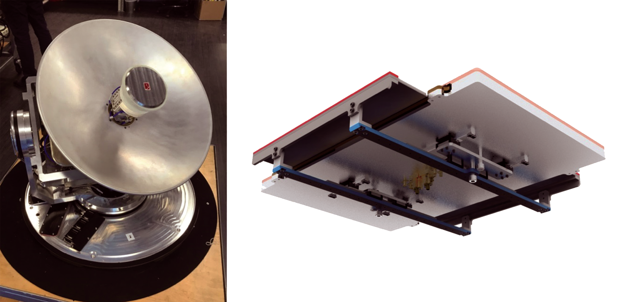 Figure 1: An EM Solutions X-band Taipan terminal (left) and flat panel prototype (right). The parabolic antenna has optimum performance in all respects if its height profile can be accommodated…but the FPA sits only a few inches high
Indeed, low profile antennas are already in common use, and appear to be particularly useful because they provide low wind resistance on aircraft and low profile on armored or command land vehicles.
But as they say at the races, its horses for courses. You cannot expect a sprinter to win the Kentucky Derby or the Melbourne Cup any more than you could expect a stayer to win the Hong Kong Mile.
A parabolic antenna, especially in a gimballed terminal such as EM Solutions’ Taipan land mobile terminal (Figure 1) or Cobra maritime terminal, can provide exceptional multi-band or broadband performance, and constant gain and thus data rate over a complete range of look angles.
However, if the requirements for low profile trump all other requirements (to continue a gambling analogy), then be prepared to compromise on one or more requirements — which might be bandwidth, data rate, or range of look angles, dependent on the particular technology deployed. Flat panel antennas, or even low profile two-axis mechanically steered antennas, will never have the same bandwidth or gain compared with their parabolic equivalents, and will suffer lower data rates at off-axis look angles.

There are several ways that a low profile comms-on-the-move terminal solution can be achieved.
Flat antenna with fixed radiation pattern, rotated mechanically in azimuth and elevation.
Terminals in this group are simple and straightforward; the flat panel antenna itself doesn’t provide the beam steering function, it requires an external mechanical subsystem to rotate the antenna body and change the beam direction. “Chopped” parabolic dishes are another type of antenna falling in this category. Because the FPA generates a static radiation pattern, the antenna can be designed with a stable and high-gain radiation pattern over a wide frequency range, although it should be noted that low profile antennas that are elongated in shape (to achieve a higher gain) will have a fan-shaped beam that may fail certain certification requirements.
Flat panel steered electronically using a phased antenna array
In this group, FPAs are designed as two-dimensional antenna arrays excited by a feeding network of signals that are varied in phase or delayed in time. Best known in radar applications, a phased array antenna can generate a focused beam useful for satellite communications, but in low volumes such systems can be very expensive.
Flat panel antenna incorporating an electronically tuned variable impedance surface
In this group of antenna arrays, the FPA is made from a tunable holographic impedance surface consisting of a large matrix of metamaterial units that are digitally controlled. The solutions in this category promise to reduce the FPA manufacturing cost compared with phased array antennas, but are faced with challenging compromises between antenna radiation performance, resolution and accuracy of steering, and sidelobe levels, as well as limited bandwidth due to the inherent narrowband properties of metamaterials.
Flat antenna made using sliding mechanical structures to achieve two-dimensional steering
In this group, the FPA is designed as a surface-wave generator by using the same theoretical framework once widely employed in optical science. A sliding mechanical structure within the FPA is used to steer the beam along the elevation angle, while a separate mechanical subsystem is required to rotate the entire antenna body horizontally to change the beam direction in the azimuthal plane. Such a design approach has the potential to reduce the manufacturing cost of the FPA, while maintaining a high-quality radiation pattern. However, the FPA will suffer degradation in its radiation efficiency as it is steered, with fluctuating antenna gain in different beam directions, and limited working bandwidth (See Figure 1).
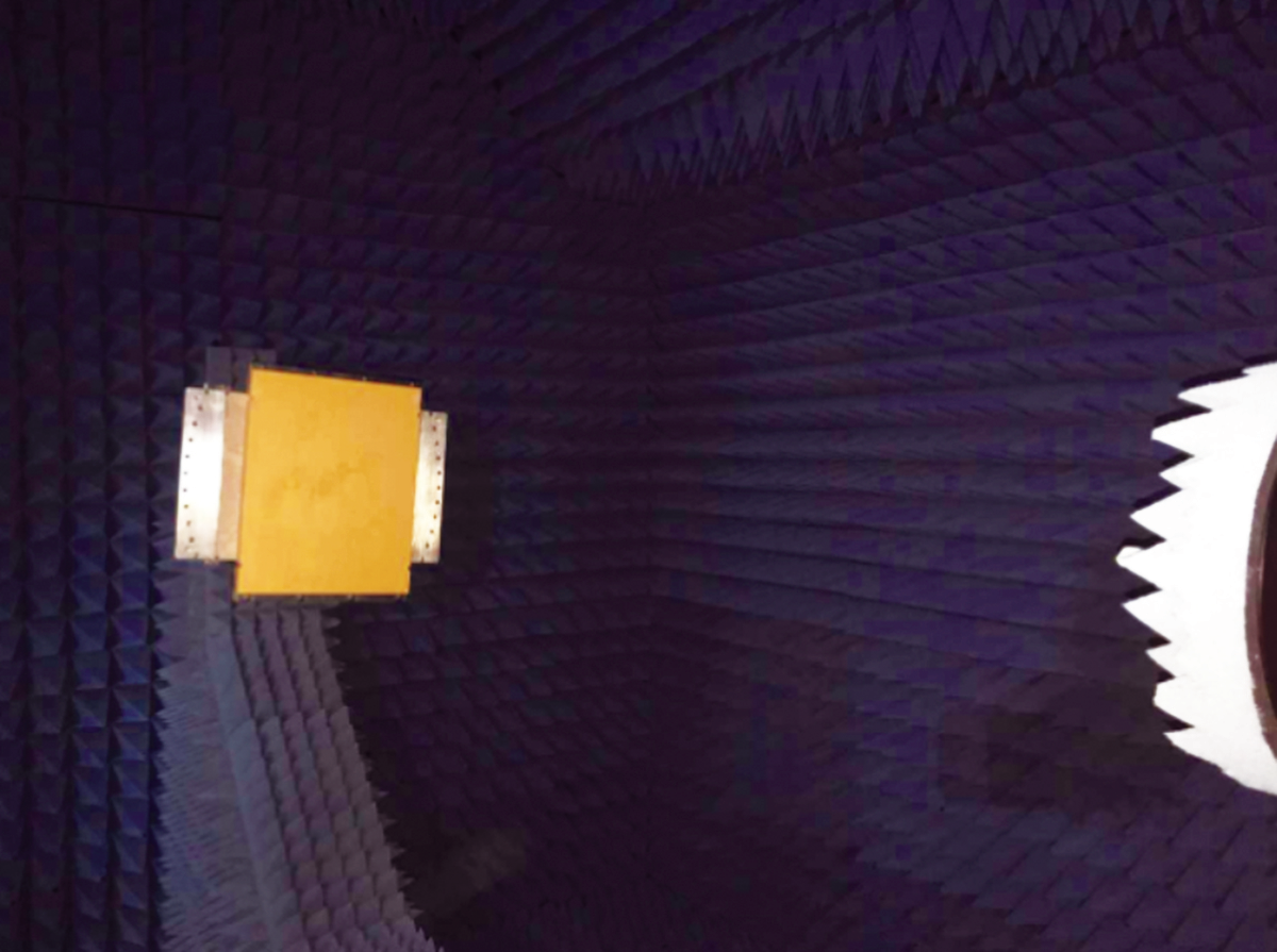
Figure 2: The EM Solutions flat panel antenna in the near field
measurement chamber
With its Cobra and Taipan OTM terminal portfolios that use steered parabolic antennas, EM Solutions has traditionally valued high antenna gain rather than low profile, and sweetened the choice by offering monopulse tracking for very robust performance over rough terrain, as well as coverage of multiple operating bands for assured communications, two advantages not yet achievable with an FPA approach.
How can these two advantages be retained in the FPA approach? At EM Solutions, we have established a long-term research collaboration with the University of Queensland (UQ) that is now beginning to bear fruit.
The EM Solutions flat panel antenna uses the fourth approach above, but attempts to retain some of the classical parabolic advantages, such as broad operating bandwidth and monopulse tracking. This flat panel might be considered a mechanically-tuned leaky wave antenna. By launching a surface wave into a flat panel dielectric waveguide, and changing a reconfigurable pattern on its top surface by mechanically shifting two patterns relative to each other, the leaky wave that radiates from the panel can be steered in any desired direction. Because the patterns themselves are etched into dielectric surfaces, the leakage can be accurately controlled. In addition, calibration of the surface can be easily accomplished and beam sidelobes well simulated and controlled. Most importantly, the panel surface itself is completely flat and inexpensive to manufacture.
The modeling of the FPA is a complex task and it is necessary to verify that the model describes the antenna pattern in space quite accurately (see Figure 2). The parameters to check are:
• That the actual antenna beam points in the direction determined from the model.
• That the antenna gain and pattern including cross polar levels are accurately predicted by the model.
• That the pointing as a function of leaky wave pattern displacements is correct.
• That the pointing and patterns as functions of frequency are correct and that beam squinting can be well predicted.
• That the limits to the pointing direction are approximately correct.
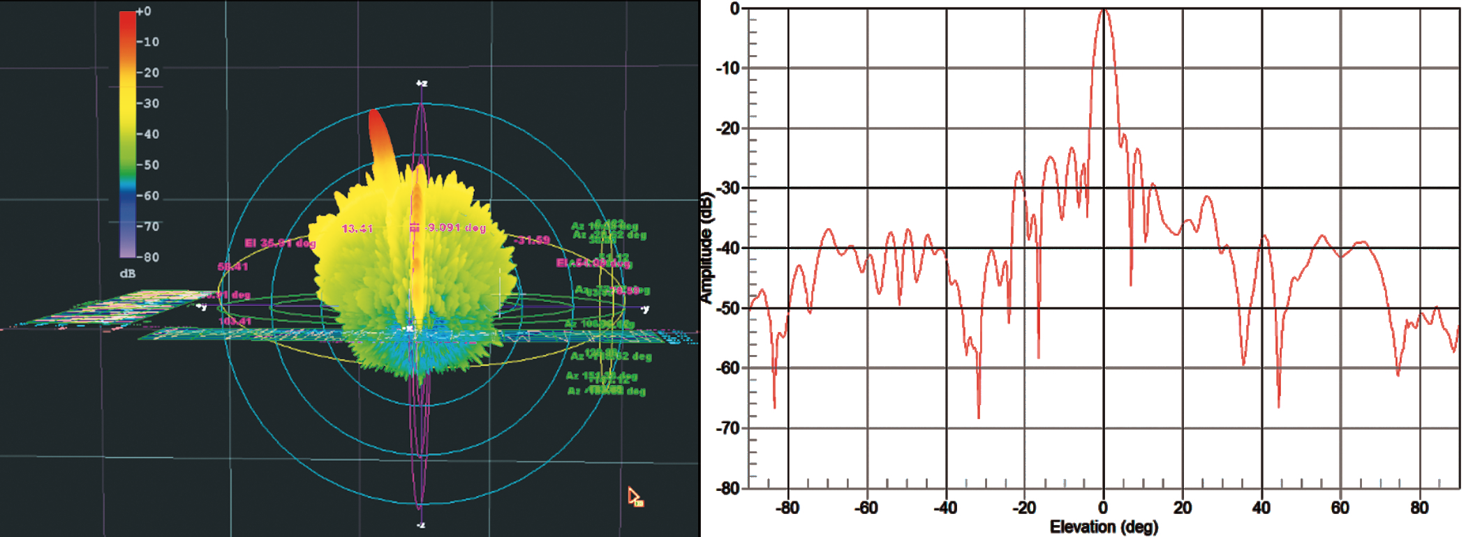 Figure 3 - Radiation Patterns Left: The normalized 3D radiation pattern shows the front-to-back ratios (20dB/div) Right: The normalized 3D radiation pattern of different beam steering directions, co-polarized LP plot (10dB/div)
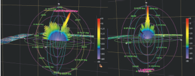
Following simulation, a variety of measurements were taken to verify performance against simulation. These include:
Radiation Efficiency
This is measured by calibrating the loss in the dielectric material itself without the patterned radiator surface that creates leakage into space, and comparing it with the loss when the leaky wave patterned surface is placed over the dielectric waveguide. The increase in loss is due to the power that is radiated into space.
We found a nominal insertion loss of 3dB without the pattern and an insertion loss of 7.5 to 10.5dB across the 18.5-21GHz band width with the pattern, so the power ‘lost’ in space varies from 4.5dB to 7.5dB. This means that 65 to 82 percent of the power is radiated.
Because the antenna directivity can also be measured in the near field measurement chamber, the resulting antenna efficiency varies from between 53 to 67 percent over the 18.5 to 21GHz frequency band. This directly determines the G/T of the antenna, and is a good result compared with most competing technologies.
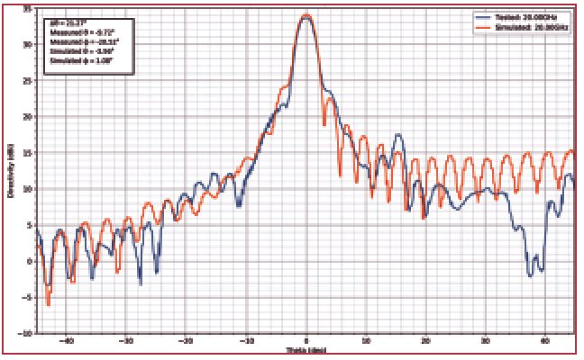 Figure 4: (X = 0mm, Y = 0mm) Measured and Simulated Antenna Pattern plots at 20GHz.
 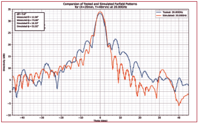 Figure 5: Measured and Simulated Antenna Pattern plots at 20GHz with a reconfigured beam steered 15 degrees off boresight.
Static Radiation Patterns
As a check on the modeling a fixed leaky wave pattern was initially used. This does not require precise positioning of the pattern on the dielectric waveguide, nor are there any problems associated with the alignment between patterns or with possible airgaps.
The fixed pattern approach was also used to determine the efficiency of the antenna. Other parameters such as beam squinting, frequency variation in gain and efficiency can also be more accurately determined with fixed patterns.
The zero-point radiation patterns were measured in the near field range at the University of Queensland across the entire receive Ka-band.
By further optimization of the feed structure and the leaky wave patterns, we expect that the sidelobe level in the transverse direction can be suppressed to more than 20dB as a result of the tapered amplitude profile realized by the feeding structure.
The side lobe level in the longitudinal direction is around 13dB, since there is no window function applied to that direction (at this point in the project — see Figures 3 and Figure 4).
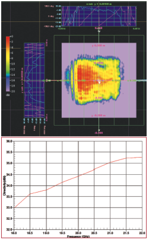 Figure 6 - Holographic Mapping of Gain vs Frequency
Steered Antenna Patterns
After the initial antenna pattern was measured at its static zero point, the leaky wave pattern was then moved a known amount to point the generated beam in a new location where the antenna pattern was again measured. This step was repeated at a number of data points.
Figure 5 compares the measured and simulated antenna patterns for one translation of the etched leaky wave pattern, and shows how the beamwidth and shape is relatively insensitive to the shift.
However, the peak amplitude is now 15 degrees offset with respect to Figure 5.
Holographic Mapping
A holographic mapping produced from the near-field scanning system can visualize the electromagnetic field distribution across the FPA aperture, which is a useful tool to diagnose any defect of the FPA and to analyze its radiation characteristics.
Figure 6 shows this mapping, and the reduction in leaky wave intensity as the incident wave travels across its surface (from left to right). It is through control of this radiation intensity and phase that a focused beam can be produced with desired sidelobe levels.
The bottom part of Figure 6 shows the increase in antenna gain with frequency, as would be expected.
Test Results Monopulse Measurements
Monopulse tracking has been used with parabolic antennas for radar and satellite terminals for over 50 years. There are various implementations of this method but the common objective is to generate what is referred to as a ‘difference’ pattern which has a null along the antenna boresight, so that the antenna can be steered by searching for the location of an exact monopulse-generated null, to indicate true boresight.
By comparing this difference pattern with the main beam, often referred to as the ‘sum’ signal, precise alignment is possible by comparing the difference to the sum, and minimizing this ratio. Additional information about how far the antenna is pointing off boresight can be extracted from the amplitude and phase of the difference signal with respect to the sum signal.
This means that the antenna pointing can be corrected virtually in one step. With circularly symmetrical antennas, it is comparatively easy to derive tracking signals along orthogonal axes. With the FPA this is not so straightforward. The monopulse circuit implemented for this version of the prototype antenna was tested for tracking along only one axis initially.
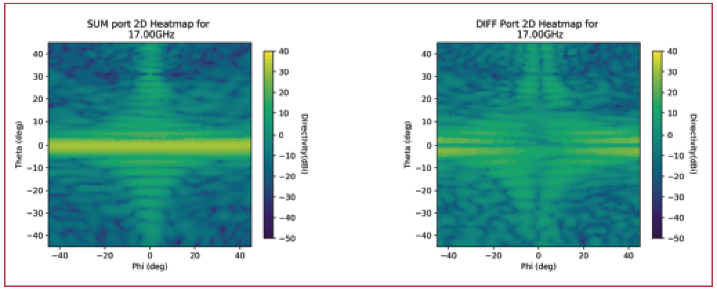
Figure 7 – “Sum” (right) and “Difference” (left) Power Levels Generated by the Monopulse Circuit.
The preliminary tests verify that the monopulse approach is capable of achieving quite good tracking in one plane.
Figure 7 shows the sum (left) and difference (right) patterns that can be generated by the FPA and used for locating true boresight. The SUM is a maximum along the main axis and the DIFF is a relatively sharp minimum along that axis. This shows that the monopulse circuit works well along that axis.
In Summary
EM Solutions is developing a true flat panel antenna with reconfigurable beam steering, initially to cover Ka-band frequencies.
The company has been able to confirm that an acceptable pattern can be produced using the antenna, and that the pattern can be steered by shifting the leaky wave surface.
Furthermore, the patterns can be achieved across a broad bandwidth, and match the simulated patterns well. A way to achieve monopulse pointing has also been demonstrated.
In short, EM Solutions has found a pathway to duplicate the competitive advantages of the company’s parabolic antennas — broad bandwidth across an entire band, and highly accurate and responsive monopulse tracking in a totally flat configuration.
All the while remembering that it’s horses for courses...
www.emsolutions.com.au
Dr. Rowan Gilmore joined EM Solutions as a Director in 2007 and became Managing Director and CEO in October 2011. His role is to lead EM Solutions to achieve its vision to become recognized internationally as the leading designers and manufacturers of the most innovative and highest quality microwave product technology.
Rowan will be known to those in the microwave engineering community who have attended his short courses on microwave circuit design and RF wireless systems offered by Besser Associates and CEI Europe since 1990.

His previous experience includes Vice President, Engineering at Compact Software, where he introduced the world’s first harmonic balance nonlinear circuit simulator, and as Vice President, Network Services Europe for SITA-Equant, the global airline IT company, now part of France Telecom’s Orange network. Most recently he was CEO of the Australian Institute for Commercialization, where he helped numerous start-up companies and worked to accelerate technology transfer between research institutions and industry.
Rowan obtained his D.Sc. in Electrical Engineering from Washington University in St Louis. He is an adjunct professor of both Business and Electrical Engineering at the University of Queensland, and was elected a Fellow of the Academy of Technological Scientists and Engineers in 2009.