
Militaries around the world are seeking “assured communications.” Assuredness comes from multiple factors, including redundancy in components and systems that are resilient to weather, attack, or congestion — the ability to automatically switch frequency bands and satellites can help increase assuredness.
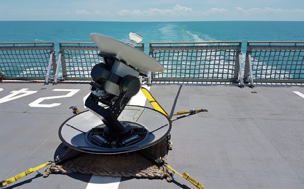
An EM Solutions X-/Ka- multi-band maritime terminal undergoing sea trials off the Barrier Reef in Australia. Photo is courtesy of EM Solutions.
So, too, does interoperability between satellite systems.
High throughput satellites in both Ku- and Ka-band frequencies are being launched with increasing regularity. To the ground terminal manufacturer, building a terminal at one frequency rather than the other involves more than a change in receiver (LNB) and transmitter (BUC) hardware and settings: a build frequently involves accommodating a change in signal polarization as well.
The polarization of an electromagnetic wave is defined by the orientation of its electric field vector. For satellite systems, the signal polarization can be either linear or circular. Typically, satellite signals at Ku-band are linearly polarized (LP); that is, their electric fields, which are perpendicular to the direction of signal propagation, are aligned in a single direction (for instance, north-south or east-west for a signal approaching the equator from space). This means the receiving ground antenna feed must also be appropriately rotated to ensure the electric field is captured at the correct angle for maximum signal. This makes implementing mobility solutions difficult in Ku-band.
Most satellite signals at Ka-band are circularly polarized (CP), which means the electric field rotates clockwise or anti-clockwise looking along the direction of propagation, called right hand circularly polarized (RHCP) or left hand (LHCP) respectively. Once the receiving antenna is aligned for maximum signal by pointing along boresight to the transmitting satellite, CP avoids the need for rotation of the feed to any particular transverse angle.

This simplifies the task of signal capture for a Satellite-On-The-Move (SOTM) SATCOM terminal, as the antenna need ‘only’ be steered toward boresight, while further adjustment of the transverse feed angle (around boresight) is unnecessary. That is not the case with linearly polarized Ku-band signals. A CP signal also rejects the first reflection, which will be polarized in the opposite direction, offering some protection from a strong reflection.
For a wave that is close to ideal circular polarization, but not perfect, its trajectory will appear slightly elliptical. The axial ratio (AR) is given by 20log(Vmax/Vmin) where Vmax and Vmin are the amplitudes of the total signal on the major and minor axes respectively.
In the case of pure LHCP or RHCP, Vmax and Vmin are equal and, in this case, the AR =0dB. An AR up to 1dB is considered to give a very good CP wave and is generally a difficult specification to meet.
AR values of ~2dB are more realistic. When Vmax >> Vmin but Vmin is not exactly zero, the wave can now be considered (almost) linearly polarized. The cross polar ratio (XPD) is given by 20log (Vmax/Vmin).
XPD values of 30 dB are considered very good for nominally linearly polarized signals, while 25 dB is a more realistic value. Note that the propagation path through the atmosphere can affect the polarization, particularly if there are water droplets or rain along the path.
Because vertical and horizontal LP, or right and left CP signals, are orthogonal to each other, satellite systems will use alternating polarizations for separating adjacent transponders, or to separate the up and down links to reuse the same frequency.
Detection of circularly polarized signals requires careful design to ensure that only the right-hand mode (say) is extracted from any residualleft-hand mode that could be a component of the overall received signal (in a similar way to the horizontal and vertical modes with LP). Any additive component from an imperfect cross mode will cause deterioration in the axial ratio or cross polar rejection, and the interference will lower the signal to noise ratio.
Various systems may also use different types of polarization, even if they operate in the same band. For instance, some Ka-band satellites are linearly polarized, rather than circular. Therefore, it is often required for a terminal to be able to switch between polarizations, which is typically done by using waveguide switches or manually changing ports.
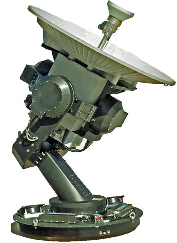
The X-/Ka-multi-band Cobra terminal houses its electronics and polarization system in an RF “can” mounted directly behind the antenna. Photo is courtesy of EM Solutions.
For LP systems, the feed network or even the complete antenna may be made so it can be mechanically rotated. All of these methods complicate the mechanical layout of the feed network and usually increase its size and mechanical complexity. These are major considerations for small mobile terminals. A more simple and robust conversion mechanism to switch between LP and CP and their two orientations is required.
Switching Between Satellites with Different Polarization Types
A rotating circular vector can be created by summing two equal amplitude sinusoidal x- and y-vectors phased 90 degrees apart (in time). Circular polarization can be achieved the same way in terminals, using a device such as a quadrature hybrid coupler that splits an incoming electrical input into two equal signals 90-degrees apart in phase, and then recombining those two signals geometrically along perpendicular x- and y-axes. A receiver circuit works the same way, in reverse.
Using a combiner in this way, a CP receive antenna feed can be used to detect an LP signal; however, one of the two paths in the circuit above will be null and the incoming signal-to-noise ratio will be 3-dB lower than if the proper detection circuit were used. Similarly, an LP feed (say, vertical) can detect the CP signal component along this axis, but be unable to detect the second component perpendicular to it (which would be horizontal). Such a halving in sensitivity can be fatal in satellite terminals.
To overcome this situation, EM Solutions terminals are designed with a novel electronic polarizer in the receiver that automatically adjusts for the polarization of any received signal — RHCP, LHCP and LP of any angle without any significant degradation in S/N in the receiver. The same polarizer in the transmitter can also be set up to work with either RCHP or LHCP without any drop in EIRP, or set up for LP of any angle.
Previously, to receive a linearly polarized signal on the move, the entire dish and feed network had to be rotated in order to align with the vertical or horizontal polarization of the satellite. Now, this rotation can be eliminated using EM Solutions new polarization module that also avoids rotation of any of the interconnecting cables.
In the new system, the receive path is corrected electronically using an Rx Polarization Module that automatically adjusts for the correct signal phasing using electronic phase shifters. As noted above, if a single linearly polarized path were used to extract the carrier or beacon signal, then this would be typically 3 dB below the maximum signal obtainable.
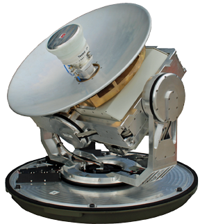
An EM Solutions X-band Taipan terminal for land-based satellite communications on the move. Photo is courtesy of EM Solutions.
Additionally, with the new system, orthogonal linearly polarized paths created in the antenna feed referred to as H and V are first combined in a 3dB quadrature coupler and then phase adjusted to realize the receive path. This ensures both components of a signal of any polarization are captured and maximizes the signal to noise ratio of the signal.
For the transmit path, the high power levels create an additional level of difficulty. Electronic phase shifters need to be operated at relatively low power levels to avoid non linear effects. The relatively high insertion loss of such devices also means that they should be located where gain is low power and low cost. This requires that the relative phase shift along the two paths of the polarizer eventually includes both high gain and high power stages, and it is difficult to calibrate these to maintain an accurate phase relationship over frequency, power and temperature.
However, the distributed nature of high power solid state amplifiers is well suited to incorporating electronic polarization in the transmit path provided the phase stability issue can be resolved. Even so, a system set up to transmit LP at an arbitrary angle cannot be used to generate CP without a 3 dB drop in power, unless a complex array of switches is used which is not an elegant solution.
Benefits to the User
The polarizer above was developed to satisfy a requirement for EM Solutions terminals to provide assured communications, by tracking and communicating using satellites in both X- and Ka-band, military and commercial and with beacons of different polarizations.
Switching between LHCP, RHCP, and LP needs to be automatic to provide the versatility and flexibility expected by today’s military forces.
EM Solutions latest Cobra tri-band terminal makes the best use of military and commercial satellites, offering simultaneous communications in X- and Ka-band on the WGS satellite system and providing fallback to the Inmarsat GX system for assuredness. Such global interoperability, flexibility, and assuredness of satellite communications requires innovations like the electronic polarizer module that EM Solutions is renowned for.
www.emsolutions.com.au/
Dr. John Ness is the founder and Chief Technical Officer of EM Solutions. John is a veteran of the microwave industry and continues to be active in the design and measurement of complex RF circuits, antennas and waveguide structures. His contributions include multi-band antennas, waveguide power combiners, and established two companies.
Marshall Lewis is an RF engineer at EM Solutions. A winner of the University of Queensland medal for academic excellence, Marshall is rapidly becoming one of the company’s experts in the design of circuits and systems used in satellite communications.