
In the US for Ku-band, the FCC defines specific pointing error requirements and antenna Effective Isotropically Radiated Power (EIRP) spectral density limits for Vehicle Mount Earth Station (VMES) systems.
Outside the US other regulators impose typically higher EIRP spectral density limits, but always some limit to protect adjacent satellites. Other frequency bands are subject to limitations on EIRP spectral density which can be radiated towards adjacent satellites, but the VMES requirements provide an ideal example of how to maximize broadband SATCOM performance. Because of that, a description of how to satisfy the VMES requirements is just as applicable on other frequency bands and in other countries with various regulatory requirements.
A VMES system operates from motorized vehicles that travel primarily on land, receive from and transmit to geostationary FSS Ku-band space stations and operates within the US. VMES terminals can include military SATCOM-On-the-Move (SOTM) applications as well as stationary satellite news gathering (SNG) terminals also referred to as SATCOM-On-the-Pause (SOTP). Alternative licenses exist, but a brief summary of high-level VMES Ku-band FCC requirements will be the basis for this article.
VMES Classification
Classification A: Each VMES transmitter shall maintain a pointing error of less than or equal to 0.2 degrees between the orbital location of the target satellite and the axis of the main lobe of the VMES antenna. If met, the vendor is qualified to receive an All Satellite license (ALSAT) with no restrictions.
• Transmitter must abide by VMES EIRP spectral density limits.
• All emissions from the VMES shall automatically cease within 100 milliseconds if the pointing error of the VMES antenna exceeds 0.5 degrees, and transmission shall not resume until such angle is ≤ 0.2 degrees.

Classification B: Each VMES transmitter shall declare a maximum antenna pointing error that may be greater than 0.2 degrees provided that the VMES does not exceed the required off-axis EIRP spectral density limits, taking into account the antenna pointing error.
• The vendor will receive a limited license.
• All emissions from the VMES shall automatically cease within 100 milliseconds if the pointing error exceeds the maximum declared pointing error and shall not resume transmissions until such angle is less than or equal to maximum declared pointing error.
Transmitter EIRP Spectral Density Limitations
The requirement by the FCC limiting a transmitter’s EIRP spectral density can be affected by three parameters:
• Antenna Transmit Gain (antenna specific)
• Antenna Uplink Power (antenna/modem specific)
• Carrier Bandwidth and Spread Factor (modem specific)
Antenna transmit gain is fixed by aperture size and cannot be modified after the antenna design is complete. The remaining two variables are dependent on the end-user application.
In order to meet EIRP density limits, the user can either: (1) manage total uplink power or (2) change the uplink modulation by modifying modulation type and/or FEC coding or additive spreading to increase the modem’s spreading factor and leave total uplink power unchanged.
Uplink power is directly correlated to uplink data rate, whereas carrier bandwidth is directly related to space segment cost. A 3dB reduction in uplink power results in a 50 percent reduction in data rate, assuming the same modulation format, while a 3dB increase in spreading results in a doubling of leased bandwidth cost.
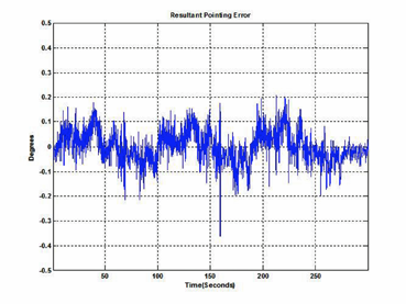
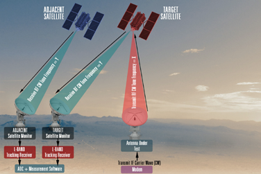
Figure 1. Pointing Measurement Setup & Measured Results.
Since the future of technology is driving data rate demands higher and higher and apertures as small as SOTM terminals are constrained by EIRP spectral density rather than total uplink power, the user community is more likely to pay for additional bandwidth cost rather than reduce the transmit uplink power and reduce the data rate. If pointing error exceeds 0.2 degrees, the user is forced to back off on uplink power and compensate by increasing the modem spread factor. Therefore, pointing error performance must be addressed in order for the customer to be aware of the total life cycle cost of a multi-node network terminal and understands the impact of various terminal parameters.
What Is Pointing Performance?
Pointing performance of any SATCOM antenna system is defined by the unit’s ability to keep the antenna dish pointed directly to the satellite during operation. For SOTM applications, this requirement is challenging due to the complex engineering required to steer the antenna’s transmit beam to the satellite with high availability during vehicle motion.
Typically, a SOTM antenna is under a radome so wind is not an issue. However, for SOTP operation, the challenge exists in holding an antenna position during heavy wind gusts and the general difficulties incurred with pointing antenna positioners that are often engineered to meet low cost targets.
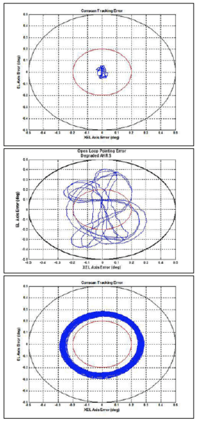
Figure 2. Operational Mode Comparison.
Search, acquisition, stabilization, scanning, tracking, and coasting are all parts of the pointing function. Pointing error, a measure of the radial angular error from the satellite, comes directly from the state variables of the control system.
Measuring Pointed Performance
Various methods can be used to ascertain pointing error of an on-the-move terminal. An effective, unit under test (UUT) agnostic method utilizes two independent large aperture terminals to measure adjacent satellite interference. The UUT transmits an RF signal to the target satellite, being monitored by large antenna #1, while large antenna #2 monitors the signal level of the adjacent satellite.
The procedure measures adjacent satellite interference (using signal information from both large antennas to correlate atmospheric signal drops) and back calculates pointing error within 0.05 degrees of resolution (well within the VMES limits). Figure 1 illustrates the test method setup where data shown in Figure 2 is actual measured data from an off-road pointing error test.
What Impacts Pointing Performance?
Many system performance criteria affect a terminal’s pointing performance. These include:
• Operational mode and inertial navigation system (INS) selection
• Sensor and stabilization performance
• Antenna stiffness
Since the VMES specification limits antenna EIRP spectral density limits to mitigate adjacent satellite interference (ASI), pointing error and antenna EIRP spectral density are directly related. Pointing accuracy also impacts bandwidth cost and the overall cost of ownership. Each of these latter effects is detailed in the subsequent section.
Operational Mode & INS selection
SOTM and SOTP antenna terminals primary responsibility is to close a satellite link and provide maximum traffic bandwidth while functioning in on-the-move and on-the-pause applications, respectively. Closing this link can be performed in two primary modes of operation:
1. Open-Loop Positioning (Point Mode) where the antenna is paired with an INS to continuously position the antenna’s line-of-sight (LOS) vector to the target
2. Closed-Loop Tracking (Track Mode) which uses the receive signal from the satellite to keep the antenna LOS vector oriented correctly during system-level operation
Open-Loop Positioning involves closing the antenna’s gimbal position control loops around the gimbal position sensors. Typically, an antenna control unit (ACU) uses the satellite coordinates, vehicle GPS location, and INS information to calculate accurate gimbal position commands.
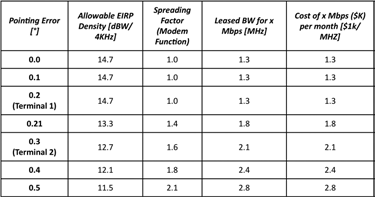
Table 1. Cost of Leased Bandwidth as a Function of Pointing Error (20-inch Aperture)
The accuracy of the INS data and effectiveness of antenna calibration techniques are direct drivers of pointing accuracy and acquisition time. High precision INS are usually the most cost intensive as they require very accurate internal sensors (gyroscopes and accelerometers) in determination of vehicle attitude during stationary and dynamic on-the-move operation.
Closed-Loop Tracking is a control function that keeps line-of-sight on the target satellite using the satellite’s receive signal. The antenna’s gimbal position control loops are now closed around a tracking receiver instead of the gimbal position sensors.
Track Mode can commence in various ways, but tracking antennas still require some attitude solution (INS, magnetometer, tilt sensors) that are relatively accurate such that acquisition and re-acquisition times are minimized. The level of precision drops from the high precision variety as does the procurement cost.
In Track Mode, once the satellite signal has been detected and adequate carrier-to-noise has been achieved for Track Mode to commence, the INS solution is “let go” for azimuth and elevation purposes as the LOS vector is oriented strictly from the satellite receive signal. FSS Ku-band operation, as linear signal polarization is used, does require a polarization axis, thus pol stabilization, where the vehicle’s pitch and roll information is used for polarization (pol) alignment and cross-pol isolation. The topic of cross-pol isolation is beyond the scope of this article but is an important criterion in selecting the correct SATCOM terminal.
Point Mode and Track Mode differences are illustrated using a six degree-of-freedom, non-linear antenna simulation to characterize performance. Point Mode performance is shown for both precision and low-cost INS, while Track Mode is shown paired with a low-cost INS. In all cases, the antenna configuration and base motion inputs (off-road course) are identical. The red circle illustrates the 0.2 degrees VMES pointing limit while the blue trace is the antenna LOS pointing vector during operation.
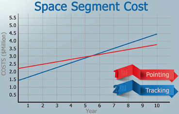
Figure 3. Space Segment Cost Analysis.
Each plot provides notable detail in regard to antenna mis-pointing, system performance, VMES compliance, and overall cost of ownership. First and foremost, the terminal operating in Point Mode with the high precision INS, Terminal 1, has the smallest pointing error compared to the other operational configurations. In reference to the VMES specification, Terminal 1 would fall under Classification A.
The terminal in Point Mode with low-cost INS, Terminal 2, is able to point within 0.4 degrees. Lastly, the terminal in Tracking Mode with low-cost INS, Terminal 3, is tracking within 0.3 degrees and is using the same INS as Terminal 2. Terminal 2 and Terminal 3 fall under Classification B.
Antenna terminals using high precision INS, Terminal 1, often have the largest procurement costs but result in overall reduction in leased bandwidth cost due to the limited spreading required by the modem to meet the EIRP spectral density limits. Total cost of ownership is mainly dictated by the bandwidth requirements of a satellite network and will be further detailed.
The data also illustrates that Track Mode operation is often preferred over Open-Loop Pointing with a lower-cost INS option. Many communication platforms where a high precision INS is cost prohibitive have antenna terminals that are considered tracking-only terminals. As stated, the drawbacks of these terminals involve the impact on space segment cost.
Sensor & Stabilization Performance
A sensor (also called detector) is a converter that measures a physical quantity and converts it into a signal which can be read by an observer. A servo (i.e., servomechanism) is a device used to provide control of a desired operation through the use of feedback.
SOTM and SOTP antennas use servo architecture to provide line of sight control. Feedback is provided by sensors that are mounted to the pedestal and positioner. The antenna design is dictated by customer specifications that detail the concept of operations (CONOPS).
CONOPS for SOTM terminals include road course dynamics, power requirements, travel ranges, wind speeds, and other factors that fall under servo, stabilization, and pointing. These are the primary drivers that impact sensor and servo selection.
SOTM antennas optimized for limited dynamic motion scenarios will often have difficultly handling rugged off-road terrain that is typical for military environments. Conversely, SOTM terminals built for off-road conditions with significant base motion are over-designed for commercial and “improved” road conditions.
This is for the benefit of the customer that the terminal is built for the desired application. A design that is either over or under designed will have long term cost and link availability implications. The same is true for SOTP terminals in terms of identifying the CONOPS and designing the system accordingly.
Antenna Stiffness
Overall antenna system stiffness is another key contributor for both SOTM and SOTP terminals and their ability to point and track. Antenna system stiffness is the rigidity of the sum of each of the sub-system contributors. These sub-system contributors can be structural or mechanical and consist of components such as the main reflector, sub-reflector (if applicable), reflector support structure, feedboom (if applicable), feed, gimbals, and vehicle mounting interface.
Typically, values such as spring rates, torque constants, backlash, and windup are either calculated or measured and are required inputs to determining how well an antenna will be able to point and track either dynamically or statically in the wind.
A detailed discourse on these values and how they are calculated or measured is beyond the scope of this article.
However, as mentioned above, understanding the CONOPS of a system is paramount to the proper selection of the correct system components such as motors, gearboxes, and drive systems, as well as determining how structurally rigid a system is required for implementation. The level of positional accuracy of a gearbox or bearing determines the accuracy required in a position feedback sensor. Just like sensor selection, increasing a system’s stiffness is achieved by adding material which translates to weight and cost. A system that is over-designed to its CONOPS will unnecessarily drive up the cost due to excessive material and high performing components. The takeaway from this is to understand the required system CONOPS in order to optimize performance per cost.
Total Cost Of Ownership
Pointing performance has an immediate impact on the cost of leased bandwidth and overall cost of ownership for a multi-node network. The space segment cost of a multi-node communications network includes
the following:
• Procurement cost of antenna terminals
• Lease cost of carrier bandwidth for desired data rate
The procurement cost of an antenna is dependent on many factors and is beyond the scope of this article. The lease cost associated with carrier bandwidth is directly related to pointing error. Table 1 illustrates
the following:
• EIRP spectral density is limited by pointing error per the VMES specification
• The impact on the spreading factor assuming fixed uplink power and antenna gain
• Cost associated with different grades of pointing error
The costs detailed in the table are generic and are used for illustrative purposes only.
Using the simulation results from the operational mode analysis, a total cost of ownership comparison is completed for Terminal 1 and 3. Rarely is Terminal 2 used for operation. Cost estimates for Terminal 1 and 3 are $100K and $50K, respectively. The cost of bandwidth is assumed to be $1K per 1 MHz of bandwidth.
Terminal 1 incurs a larger procurement cost due to the high precision INS. Terminal 1 uses a spread factor of 1.0, resulting in a leased bandwidth cost of $1.3K per month. Terminal 3, using a spread factor of 1.6, would incur a monthly lease cost of $2.1k. This is approximately a 60 percent percent rise in leased bandwidth cost due to a 0.1 degree increase in antenna mis-pointing. A space segment cost analysis was completed for a ten node network over a ten year span using Terminal 1 and Terminal 3 for comparison—see Figure 3, which shows that after approximately six years, Terminal 1 with the higher initial procurement cost, will be a more cost effective network solution. Of course, the generic transponder lease cost of $1k/Month is likely optimistic, meaning that the Total Cost of Ownership of a network employing Terminal 1 will usually happen much sooner than six year
Antenna specific parameters including INS precision, operational mode, servo performance, and stiffness all directly impact the leased bandwidth cost billed to the end customer for terminals required to meet FCC VMES requirements. Similar analyses for SOTM terminals operating on different satellite operating bands or under different regulatory requirements have similar EIRP spectral density and pointing impacts—they simply happen at different relative power levels.
Examples illustrated in this article reveal the advantages of lower cost Track Mode terminals at the time of procurement as well as the accelerated cost implications over the life of the system. The discussion on servo and sensor selection illustrates the importance of system level requirements and sensor precision. The discussion on antenna stiffness as well as mechanical and structural considerations shows the impact effect on pointing error and thus cost. Although rarely specified by a customer, total cost-of-ownership for a communications network is a critical aspect in deciding which on-the-move or on-the-pause antenna terminal is best suited for the end user.
www.gdsatcom.com

Rohit Murthy is the Technical Director for General Dynamics Mission Systems’ SATCOM On-the-Move (SOTM) and SATCOM On-the-Pause products group. He is responsible for product configuration and technical research, product business development, and technical lead for IRAD efforts.
Mr. Murthy has been involved in engineering and design of SATCOM, servo, and stabilization systems for over 11 years. His product expertise includes systems engineering, stabilization and control for SOTM pedestals as well as software development for stabilized platforms. Mr. Murthy was also involved in establishing General Dynamics Mission Systems’ communications on-the-move product line and has led various iterations of the product line in creating the industry-leading line of ground SOTM systems. Mr. Murthy also plays key roles in business development including proposal development and guiding new solutions for new markets.
Mr. Murthy holds a BSEE and MSEE from the Georgia Institute of Technology in Electrical and Computer Engineering with a specialization in Controls, Stabilization, and Signal Processing.

David Svesko is the Deputy Program Manager of Engineering for General Dynamics Mission Systems’ SATCOM On-the-Pause products group. In this role he is responsible for new product development, sustaining engineering product improvements, proposals, customer training and manages a team of design engineers.
Mr. Svesko has worked at General Dynamics Mission Systems for over 10 years and has held a number of roles including design engineer, test engineer, and systems engineer on various products spanning from small antennas (1.0m) to large fixed Earth stations (16.4m), developed and embedded antenna control systems into tactical fly-away antennas, and was a project engineer for the Atacama Large Millimeter/submillimeter Array (ALMA) in its first year of production.
Mr. Svesko holds a BSME degree from Rose-Hulman Institute of Technology with a concentration in Aerospace Engineering.