
To maximize satellite network quality and uptime and optimize costs, satellite Earth stations in regions prone to snow need
de-icing systems to protect their antennas from the accumulation of snow and ice on the antenna.
In some locations, an antenna de-icing system is a “must-have” in order to prevent significant losses in signal and increases in network cost due to ice and snow, especially when using Ku-, X-, and Ka-band. The most effective and cost-efficient solution for larger, fixed-site antennas, such as Satellite Enterprise Terminals (SET), and gateways is to employ hot air de-icing.
This article discusses improvements under development that promise to bring Earth station operators new gains in network control, operational and energy efficiency.
Why Prevent Snow and Ice?
On top of the large atmospheric and rain fade effects, especially at Ku-, X-and Ka-band frequencies used by the Wideband Global Satellite (WGS) system, the accumulation of snow, particularly wet snow, ice, or freezing rain on satellite Earth station antenna reflectors and feeds, can cause significant signal loss effects. These include:
• Attenuating the satellite signal
• Increasing the system noise temperature of the antenna
• Reducing antenna efficiency, gain, and focus, due to distortion of the antenna caused by uneven surface temperatures. Together these effects (reducing antenna gain and increasing noise temperature) reduce the G/T Figure of Merit performance, which is critical for closing satellite links.
• Rain and Ice also cause de-polarization depending on particles and raindrop shapes, attenuating the signal, especially if present in the feed aperture.
• The moisture composition of snow can vary, from dry snow to wet snow, sleet, to a mixture of snow and freezing rain.
Freezing Rain
Freezing rain droplets can turn into ice on impact with the ground or an antenna reflector. The accumulation on the bottom half of a reflector of ice formed from freezing rain can also de-focus the reflector temporarily. For example, NASA Researchers have observed in a test of Ka-band terminals that “accumulation of snow on the parabolic reflector of an antenna or the formation of a glaze layer during freezing rain events can significantly degrade the received signal.”
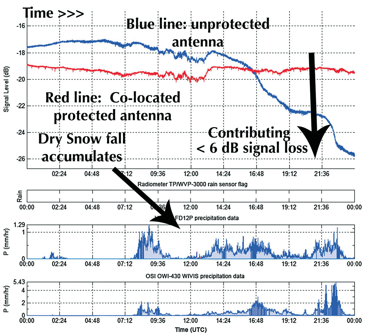
Figure 1. Courtesy of American Geophysical Union: Dry Snow Effect on Ka-Band Antenna (Black Text & Arrow Annotations Added for clarity).
Dry Snow
Although dry snowfall minimally contributes (i.e., under 1 dB) to atmospheric losses (unlike rain), in a typical Fixed Satellite Services (FSS) link, the effect of snow on an antenna can significantly degrade the signal. Accumulation of snow on the bottom half of an antenna reflector can cause an uneven temperature distribution across the reflector surface, and therefore temporarily distort the parabolic geometry and disturb the focus of the antenna. The effects can be quite large in the higher frequencies, such as Ka-band, used by the Wideband Global Satellite (WGS) system, as well as X-, and Ku-bands, because tight surface tolerances are required for narrow beam widths at higher frequencies.
As an example, one research study showed that, due to the accumulation of snow in the bottom of an antenna reflector (2.4 meter and 1.2 meter reflectors in this case), uneven surface temperatures caused reflector de-focusing, creating signal losses that were as high as 6 dB at 20 GHz Ka-band. This is illustrated in Figure 1, where the blue line in the top panel shows a 6 dB reduction in received signal power after dry snow accumulated on an antenna and distorted its focal point and efficiency, and reducing the gain. The red line shows the signal gain during the same period, through a co-located antenna that is shielded from the elements, and experiences no signal degradation.
Such a large decrease in signal power can create a complete network outage, if the satellite link has not been engineered with the “overhead” (or link margin) to withstand such a loss —or engineered to prevent its occurrence by using de-icing system. Consider how a rain immediately after the dry snow event could suddenly add additional atmospheric rain losses from 1-6 dB as the atmospheric/sky conditions change.
Wet Snow
Wet snow has a similar effect as water in attenuating satellite signals. The influence of wet snow, due to its high liquid-water content, possesses substantial energy absorption of both cm and mm wavelength signals. Accumulation of wet snow can cause significant attenuation of the signal while simultaneously increasing the system noise.
Figure 2, (Courtesy American Geophysical Union, see references) also taken from research performed at Ka-Band by the Communications Research Center Canada (CRC) shows an example of an event of wet snow accumulating on an antenna. The blue line on the top panel shows a sudden drop in the received signal by about 8 dB attributed to wet snow accumulating on a test satellite antenna. The red line represents a co-located antenna protected from snow accumulation during the same time.
Wet snow also more easily sticks to parabolic reflectors and antenna feeds. Researchers have observed that accumulation of snow on the parabolic reflector of an antenna or the formation of a glaze layer during freezing rain events can significantly degrade the received signal (measured in 20 GHz range).
Antenna Wetting
Water on the main reflector, and even more critically on the feed aperture, is another potential source of loss at 20 and 30 GHz. Rain on a reflector can create a distorted reflector surface that reduces the antenna gain by several dB in the worst case. Water on the feed aperture distorts the electric field’s distribution of the feed therefore creating a high perturbation on the feed standing wave ratio (SWR). One laboratory test measured and calculated the antenna attenuation due to surface wetting can reach 10 dB at Ka-band.
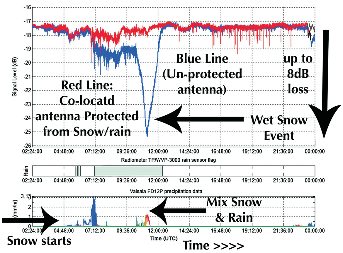
Figure 2. Wet Snow Event -8 dB Signal Loss: Courtesy of American Geophysical Union. (Annotations added in Black for clarity).
Anti-icing vs. Prevention and De-icing
Due to the growing demand for SATCOM in zones where snow and ice accumulate, demand has also increased for antenna de-icing sub-systems from companies such as Walton De-Ice, which leads the market as a supplier of snow and ice protection subsystems to Earth station antenna manufacturers and Earth stations.
Walton De-Ice systems are used in commercial and military satellite Earth stations around the globe for C-, Ku-, X-band, and Ka-band transmissions, including such networks as the WGS (Wideband Global Satellite), both through legacy Satellite Enterprise Terminal (SET) and Modernized Earth Terminals (MET) type facilities and gateways for telecommunications. The company’s systems help the DoD’s state-of-the-art SATCOMs leverage the increased throughput of the Wideband Global (WGS) satellite constellation, helping to meet the military’s demand for data, voice and video around the globe as part of the military’s communications backbone.
The Walton Hot Air De-ice system is uniquely designed to prevent snow and ice from accumulating on an Earth station antenna. The company’s patented invention uses a plenum enclosed on the rear of the antenna. Heaters (gas or electric) located on the antenna structure heat and circulate air inside the plenum, which in turn rapidly and uniformly heats the reflector surface to remove or prevent ice and/or snow from accumulating. This is shown in Figure 3.
In order to provide maximum flexibility, Walton offers electric, natural gas, and liquid propane gas heaters so a customer can make their choice, based on the cost and availability of the fuel source at their location. Depending on the Earth station site, gas heaters may offer economical operation advantages, or the low maintenance Stainless Steel Electric Heaters may be advantageous. The Plenum enclosure also hides the unsightly metal support structure and additionally prevents birds from nesting in the back structure of the antenna.
Anti-icing Techniques
Most antennas have reflector panels that are mounted onto truss supports that are then tied together. Anti-icing solutions that only heat the individual reflector panels cause distortion losses by creating temperature differentials between the reflector panels and the truss supports. Metals expand at different rates when heated. Antenna panel thickness and size varies.
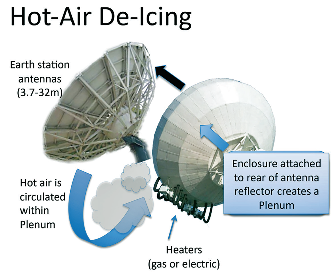
Figure 3. Hot Air De-Icing (Courtesy Walton Enterprises, Inc.)
This size difference can contribute to the uneven heating of a reflector’s metal panels with pad-based anti-icing solutions, as they tend to leave a checkerboard footprint that creates cold and warm strips on the reflector surface. Non-uniform heat applied to the antenna structure can cause de-focusing and reflector degradation. If not well designed, these kinds of products can produce high antenna gain losses (up to 6dB in Ka-band).
Unlike electric pad or heat tape anti-ice, the Walton Hot Air de-ice system heats the entire antenna reflector and back structure and uniformly distributes the heat. This minimizes the chances of reflector distortion (which can cause signal problems) caused by thermal expansion and contraction. Results show transmit and receive gain degradations at Ka-band were substantially reduced by this hot air method, down to the 0.6 to 0.75dB range for 9.2 meter to 13.2 meter Ka-band antennas, for example. That is a dramatic performance improvement when compared to the previously mentioned 6dB loss figure using other anti-icing methods.
Figure 4 shows an example of thermal measurements on an actual antenna using a Walton De-Ice plenum system. In this example, infrared photo measurements of heat across a large antenna reveals the temperature variation before, and after, the Walton De-Ice system has been activated.
Feed and Sub-reflector Protection
As noted earlier, the amount of water in reflector antennas (reflector and feed) can cause additional signal loss (up to
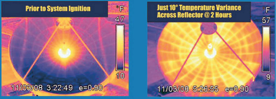
Figure 4. Image is courtesy of Walton De-Ice.
4 to 5dB) on top of the expected propagation attenuation due to rain at Ka-band, depending on the antenna size, type of antenna, and elevation angle. For both antenna sub-reflector and feed de-icing, Walton systems re-use the heated air from the Plenum, which is ducted to the feed horn and sub-reflector, using a blower. The same systems also perform rain diversion to clear the feed horn window of moisture, which can significantly degrade Ka-band, X-band, and Ku-band signals.
Heating Efficiencies
A pad-based anti-icing system must maintain heating, even if it has a temperature threshold that turns the system on automatically when a cold weather threshold is present. Thus, a heat-pad-based anti-icing solution consumes far more energy dollars than, for example, a gas-heated, Walton Plenum solution, which detects the presence of moisture and temperature, and responds by rapidly and uniformly heating the antenna, thereby conserving power.
Automatic temperature sensing and integrated control of the Walton De-Ice Plenum ensures that sufficient heat is uniformly applied to the reflector surface to minimize the thermal effects on antenna gain. The design itself minimizes thermal expansion of an antenna structure. Temperature distribution is controlled with the use of circulation fans and heat distribution systems within the plenum.
New Temperature Control / Monitoring System (TCM)
The newest TCM developments from Walton De-Ice will provide a way to passively monitor antenna surface temperatures, and a method to actively control the antenna surface temperature.
Four remote digital temperature sensors are mounted on top, bottom, and side quadrants inside the main reflector Plenum. These sensors are accurate to within + 0.5 degrees Celsius. The digital plenum temperate information is returned to a unit mounted on the Power Distribution Panel. Readings are scaled, then forwarded via a serial link to a 1RU rack-mount display panel. This gives users a rolling digital display of the operating temperature of each quadrant of the main antenna reflector so operators can confirm the proper operation of the De-Icing system.
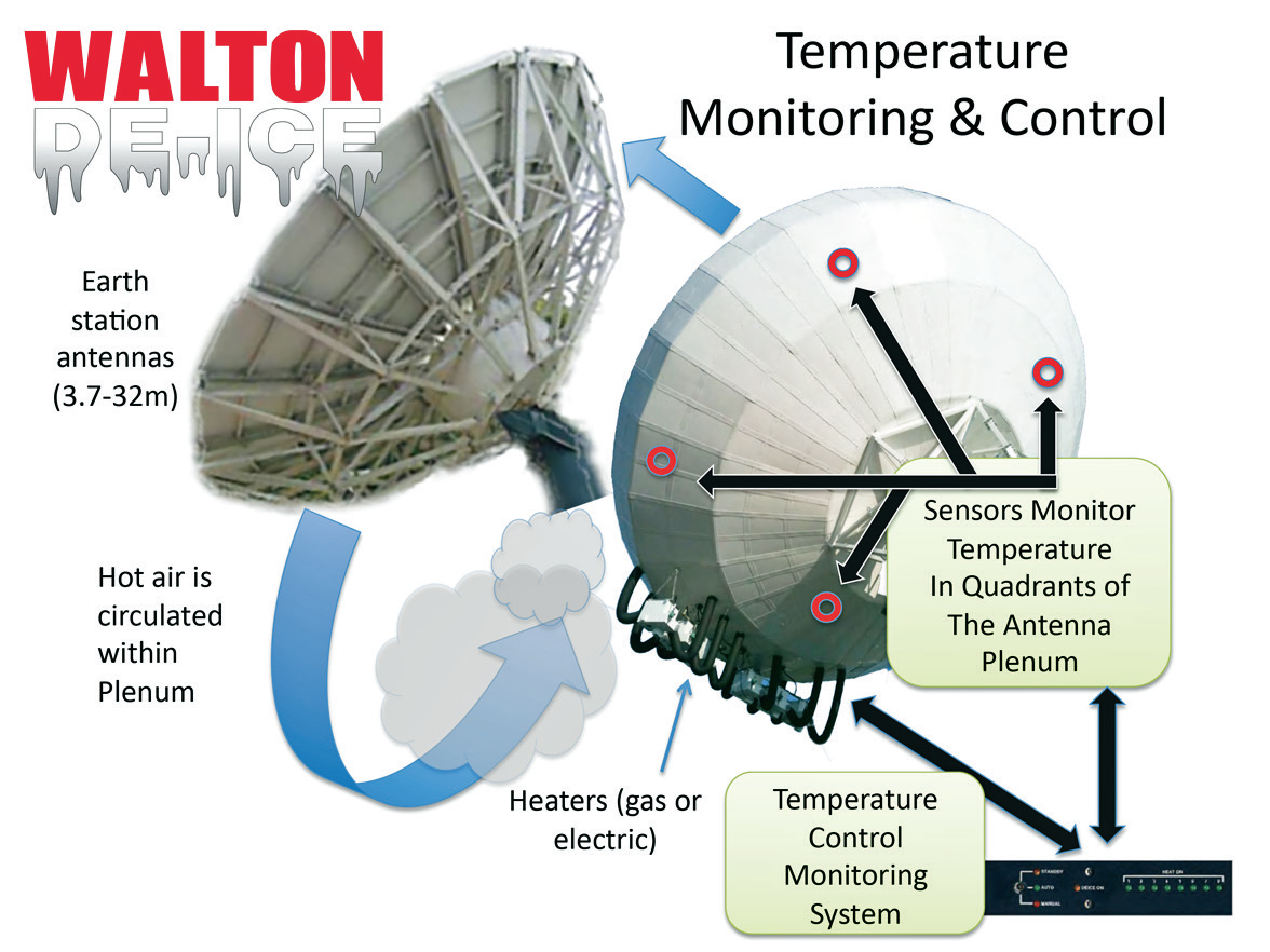
Figure 5. Hot Air De-Icing with Temperature Control/Monitoring
In addition, the new TCM systems will be configurable to replace the fixed mechanical thermal switches previously used to activate and de-activate the de-icing heaters. An on-board relay opens and closes on cue from the digital temperature sensors inside the plenum, firing the heaters as needed. Heat from all heaters in the hot-air De-Ice system will activate and deactivate at the same time. The heater fan/blower motor will operate as long as there is a call for De-Icing. This adds new operator flexibility that has not been previously available when fixed thermal switches are used. With the latest version, a user will be able to easily adjust the operating temperature of their De-Icing system. This assures reliable melt-off, while potentially reducing operating costs. Manual override for testing and special operating conditions remain available.
As discussed, higher frequency antennas require tight surface tolerances. Temperature imbalance during non-de-icing conditions can introduce uneven expansion and contraction of the main reflector. This may occur when sunshine is on a portion of the reflector and shadows are on another portion.
To help combat asymmetry, and optimize the reflector’s gain and accuracy, the new TCM system will be configurable to assist in maintaining an even surface temperature. The unit monitors the temperatures of the reflector plenum quadrants. An operator/user is able to set the desired allowable temperature difference (“span”) between all quadrants. When that number is exceeded, a relay is closed, activating circulation fans inside the antenna plenum, which disperse “hot spots” and levels the antenna reflector surface temperature differences. A rack-mount unit also offers a monitor and control interface for remote system supervision. Temperatures and relay activities can be monitored remotely.
With these new developments in Temperature Control and Monitoring, Earth station operators do not have to guess that their de-icing system is functioning properly because they can see that all the antenna quadrants are heated. Users can leverage a digital temperature display of antenna surface in real-time. This toll allows users to control reliable melt-off while potentially reducing operating costs. Saving fuel energy and bandwidth can even save lives in a conflict zone. Antenna De-Icing with new Temperature Control & Monitoring capabilities promise benefits to Earth station and SATCOM services. They can offer cost-savings opportunities to organizations running satellite Earth stations, as well as enhanced link margins and network uptime.
Hot Air De-Icing systems can also protect the new generation of Ka-band satellite networks from large signal losses (e.g., 8 dB) and potential outages on critical links. They can also enable network designers to avoid budgeting for such large power losses in the satellite link and network design. The resulting efficiency gains can translate into both capacity increases and cost-saving benefits for military SATCOM networks.
de-ice.com/

Dan Freyer is founder of AdWavez Marketing (www.AdWavez.com), a marketing communications agency uniquely focused on, and experienced in, the satellite industry. Clients benefit from his 20+ years of industry experience helping top spacecraft manufacturers, satellite operators, service providers, equipment manufacturers and integrators, and associations build their markets around the world. He can be reached at dan@adwavez.com.
References
1 Special Effects: Antenna Wetting, Short Distance Diversity and Depolarization, Roberto J. Acosta, NASA Glenn Research Center, Cleveland, Ohio 44135, Phone: 216-433-6640, Fax: 216-433-6371. E-mail: Roberto.J.Acosta@grc.nasa.gov, Online Journal of Space Communications
2 “Experimental assessment of snow-induced attenuation on an Earth-space link operating at Ka-band,” César Amaya1, José-Miguel García-Rubia2, Pierre Bouchard1, and Tu Nguyen1
1 Communications Research Centre Canada (CRC), Ottawa, Canada
2 Catholic University of America, Washington, District of Columbia, USA. American Geophysical Union, publication date: October 2014.
3 Special Effects: Antenna Wetting, Short Distance Diversity and Depolarization Roberto J. Acosta , NASA Glenn Research Center, Cleveland, Ohio 44135, Phone: 216-433-6640, Fax: 216-433-6371. E-mail: Roberto.J.Acosta@grc.nasa.gov