
Military Communications-On-The-Move (COTM) provide warfighters with mobile comms using satellites in order to connect to numerous remote locations quickly and under critical conditions1.

COTM technology allows military members to be in constant communications with one another as well as with the command structure and support facilities, regardless of the individual's location, via satellite links at X-, Ku- and Ka-band, extending to as high as 45.5 GHz. During military campaigns, personnel cannot afford to lose communication connectivity at any time, as such would disrupt the missions and, potentially, reduce survivability.
Highly desirable is that the vehicles onto which COTM antennas are installed have that antenna protected from incoming fire in order to maintain the vehicle’s COTM communications ability under hostile and adverse conditions—conventional radomes do not provide any ballistic protection whatsoever. Even small arms fire would be enough to completely disable a COTM antenna system and totally disrupt crucial communications.
Virtually all COTM systems fall into the Very Small Aperture Terminal (VSAT) category with antenna aperture sizes smaller than 3 meters; in fact, the majority of VSAT antennas range from 0.75 to 1.2 meters in diameter2.
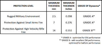
Table 1. Protection level versus thickness.
State-of-the-art military COTM antenna systems use aperture sizes as small as 0.3 meters in diameter3 and even smaller antenna sizes are desirable in order to minimize antenna visibility and vulnerability. VSAT sizes have lower signal gain, increased antenna noise temperature, broadened antenna beam width, and increased antenna sidelobes which can interfere with adjacent satellite communications.
Because of these factors, judicious design approaches must be applied to prevent further COTM antenna degradations that are resultant of a ballistic radome applied over the antenna structure. In this article, techniques and design tradeoffs are discussed.
The Wideband Of Ballistic Radome Design
The electrical design objective for a ballistic radome is -0.5 dB, or less, loss at all COTM frequency bands of interest using ballistic material thicknesses consistent with that required for the desired level of ballistic protection.
For purposes of this analysis, Dyneema® was employed based on a balance of incredibly low permittivity and loss tangent (2.3 to 2.4 and 0.0002 to 0.006, respectively). For these materials, the minimum thickness for various levels of protection are shown in Table 1.
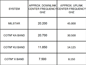
Table 2. Frequencies associated with military COTM4
Table 2 lists the downlink and uplink center frequencies of the various military COTM frequency band segments.
For a radome designer, the performance of a radome at the SATCOM downlink frequency is of more concern than at the uplink frequency. For a small COTM antenna, the G/T ratio at the downlink frequency is generally in the order of 10 to 12 dB/K.
A poorly designed radome decreases antenna gain and increases the effective antenna noise temperature, significantly decreasing G/T. Downlink frequency radome loss just cannot be compensated by inserting additional gain into the receive channel.
Such an amplifier would both amplify received signal and thermal noise—the signal to noise (S/N) ratio would not be improved. However, additional gain at the uplink can indeed compensate the effect of transmit frequency radome gain.
The equivalent instantaneous radiated power (EIRP) of 80 dBm is generally required; simply the sum of antenna gain (in decibels) and transmit power (in dBm). For the sake of preliminary design analysis discussed in this article, a loss of -0.5 dB at the downlink and uplink frequency segments was employed. (Please see Table 2.)
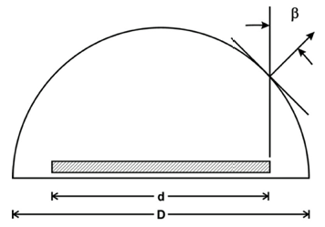
Figure 2. Definition of maximum Angle of Incidence (AOI) for an antenna within a hemispherical dome.
A COTM radome that provides full ballistic protection up to Ka- or MILSTAR frequencies is electrically thick in terms of wavelengths. Providing a radome wall concept that allows efficient multi-frequency band operation requires the use of multi-layer radome wall concepts.
In the case herein, all layers other than the thick ballistic layer are only to provide impedance matching for a broadband radome wall design.
The maximum angle of incidence (AOI) shown in Figure 2 is also a factor in determining how many layers are required; numerically, the maximum AOI is related to the ratio of antenna to radome diameter (d/D) as shown in Figure 3.
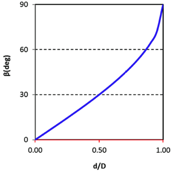
Figure 3. Maximum AOI vs. ratio of antenna to radome diameter.
Approach & Results
Radome wall loss is also a function of the layer schedule: material type, thickness, dielectric constant, and loss tangent of each wall layer. A multilayer radome wall transmission equation5 taking all these factors into account was programmed within a wall optimization computer code WALLOP.
In essence, this code searches through tens of thousands of combinations of layers and thicknesses of various material candidates to identify wall schedules that provide the required -0.5 dB, or lower, transmission loss at the various downlink and uplink frequency segments and over a range of AOIs.
For the analysis herein, the antenna to radome diameter (d/D) ratio was constrained to 0.75 so that the maximum AOI is approximately 45 degrees. For this case, a 12-inch diameter antenna would require a 16-inch diameter radome. The simplest wall multilayer configuration obtained was a single matching layer consisting of a structural foam backing up the ballistic layer, as illustrated in Figure 4. The foam layer is an interior radome insert, the Dyneema® is the fully load bearing layer.
The following results were calculated:
• A 0.6-inch thick Dyneema® layer backed up with a 1.0-inch structural foam layer (permittivity = 1.7, loss tangent = 0.001) provided less than -0.5 dB loss at all X- and Ku-band COTM downlink and uplink frequencies (circular polarization calculations).
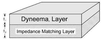
Figure 4. Radome wall concept for Ka-band and MILSTAR.
• A 0.62-inch thick Dyneema® layer backed up with a 0.8-inch structural foam layer (permittivity = 1.75, loss tangent = 0.001) provided less than -0.5 dB loss at all Ka and MILSTAR COTM downlink and uplink frequencies (circular polarization calculations).
• Simultaneous operation at all for COTM downlink and uplink frequency bands can only be achieved with a radome wall design of three or more layers.
Comms Protection
This article described the design procedures for a ballistic radome applicable to military COTM applications. With a single impedance matching structural foam layer backing the ballistic material layer, configurations were identified which provide -0.5 dB or less loss at X- and Ku-band downlink and uplink COTM frequencies, or at Ka-band and MILSTAR downlink and uplink COTM frequencies.

The authors, from left to right: D.J. Kozakoff, C. Corallo, D. Petra & W. Roovers.
Clearly, Dyneema® is also an excellent material for non-ballistic military radomes due to its unique combination of excellent EM properties, high strength and light weight. Future work will investigate wall configurations encompassing the entire range of all COTM frequency segments.
REFERENCES
1Bakshi, B., Warfighter on the Move, MilsatMagazine, September 2010.
2https://en.wikipedia.org/wiki/Very-small-aperture_terminal.
3http://www.rantecantennas.com, 2015.
4Kozakoff, D.J. and R.Ciano, “Antenna Radome Effects on High Performance SOTM Antenna Systems,” paper presented at Antenna Systems 2013, Las Vegas, Nevada, December 2013.
5Kozakoff, D.J., “Analysis of Radome Enclosed Antennas, 2nd Edition, Artech House, Norwood, Massachusetts, 2010.