
Manufacturers and designers of satellite terminals (modem, transceivers) and other wireless radio devices and networks can face significant “lab logistics” challenges in testing and validating RF signals for mesh (any to any) network topologies.
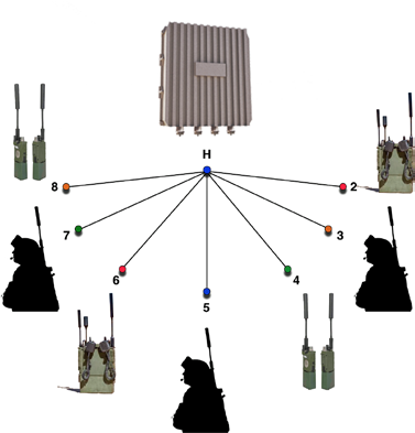
Figure 1. Hub network.
Yet, the ability of mesh networks to rapidly adapt, self-heal, and meet on-the-move and other requirements continues to create demand for mesh connections in the field. This article discusses test lab challenges and how test engineers have found they can achieve dramatically reduced test schedules and increase accuracy in RF link testing for mesh networks by using new advanced RF matrix switch test and measurement systems.
Satellite and terrestrial wireless mesh network connectivity requirements have been part of the commercial and military SATCOM landscape for years. Examples in the SATCOM world include VSAT and mobile satellite service networks for voice connectivity.
Commercial space constellations, such as Iridium, which employs inter-satellite mesh RF communications links, are part of the network fabric used for some military and COTM applications. Just one example — the US Defense Information Systems Agency (DISA) recommends DVB-RCS, which uses a TDMA mesh return path, for two-way broadband satellite systems for the US military. A number of requirements are increasing the rate of demand for wireless Mesh Networks in military communications.
Mesh networks in military field communications
The evolution of military field communications has grown to include live video, voice and data over wireless digital data networks that require very large uplink and downlink bandwidths.
Over-the-air (OTA) networks for field personnel are typically mission critical and require more than 99.999 percent resiliency in a mobile environment. The network needs to be flexible to allow the nodes to maintain connectivity as they change distance with respect to each other. These requirements are increasing demand for wireless Mesh Networks relative to Hub-based networks.
Hub-based networks
Basic hub (also known as Star) networks rely on a central server and substations to manage traffic between nodes (Figure 1). This network configuration contains single points of failure that then requires redundancy designs to maintain network connectivity.
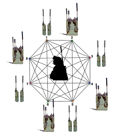
Figure 2. Full mesh network.
For some field applications, the resiliency of this network may require costly redundancies. The hub and number of substations need to be planned in advance to accommodate the changing configuration of the network where the distance between the nodes and hub and substations will change. If there are not enough substations built into the network, there is a risk that the nodes will lose connectivity.
Mesh Networks
A mesh network integrates the server capabilities into each node, so that each node in a full mesh network can have a point-to-point connection with another node, and also each node can pass the data packet along to the next node. As there are multiple paths available to make a point-to-point connection, a mesh network would always to able to make and maintain a connection even with a loss of a node.
Figure 2 shows an 8 port full mesh network where each node can have 7 direct connections.
In a real life wireless mesh network, a full mesh network is dependent upon the distance between nodes. As the distance between nodes increases or the line of sight is lost, the connection between nodes will be lost.
Figure 3 shows an example of a partial mesh network where nodes have a limited number of nearest neighbor connections due to signal level connectivity. As the nodes move relative to each other, the network connections will change depending on detected signal strength.
Nodes that move away from each other will have decreased signal level until connectivity can no longer be maintained. Nodes that move toward each other will have increased signal level to a point where a connection is made. The mesh network can accommodate these changes.
The ‘server intelligence’ built into each node is limited in comparison to a full server. In a partial mesh network, a node can have a connection with a node that is not its nearest neighbor by having its nearest neighbor pass the packet along to its next nearest neighbor and so on until the packet reaches its intended node.
Depending upon the intelligence of the server, it can route the packet along the shortest path, or, it can be randomly routed along many paths until it reaches its intended node. The number of different paths will affect the time (latency) for the packet to reach its intended node. For many networks, the latency can be critical to the speed of the network.
Time division multiple access (TDMA) networks use multiple channels to transport bandwidth signal, e.g., a 40 Gbps bandwidth can consist of 4 channels of 10 Gbps signals that are aggregated to 40 Gbps. The packets that are transmitted are expected to arrive within a predefined tolerance (which is dependent upon bandwidth) of each other.
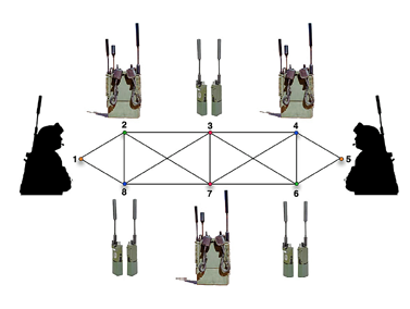
Figure 3.
If there is too much delay between packets, an error occurs and the system is required to ask for the packets to be resent. The latency tolerance can be increased using forward error correction (FEC).
A hub network relies on the substations to route the packets toward the intended target. The substations can be subject to delays due to heavy packet traffic, which can increase the transmission latency.
A mesh network minimizes latency with a one hop connection when available. Packet routing in a mesh network has additional complications as nodes can be added or dropped at any time.
Due to spatial and line-of-sight constraints, the mesh network is most likely a partial mesh configuration, where each node has a limited number of nearest neighbors. The number of nearest neighbors can change over time as the nodes move with respect to each other.
Dynamic configuration presents many challenges for packet routing, and TDMA networks need to be able to adjust to the changing number of nodes, number of nearest neighbors, etc. Latency in a partial mesh test matrix switch can be increased as additional traffic is generated since every node that is not the intended target is re-transmitting the packets.
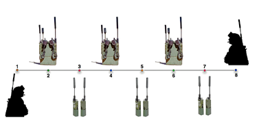
Figure 4. String network.
To ensure that the network meets the resiliency requirements, it is imperative that the firmware is able to adapt to the constantly changing network configuration. Firmware needs to be tested and verified on a network where the number of nodes, the distance between nodes and the nearest neighbor connectivity are changing. A simple base line test configuration of packet hopping through multiple nodes would be a string configuration (Figure 4).
Testing mesh RF signals
Emulation of terrestrial RF wireless (or satellite RF) signals in a test bed requires shielding the signals from outside commercial signals and other sources of Electromagnetic interference by transporting the RF signals over coaxial cable.
A mesh test system requires the use of a splitter at every device node that is interconnected to all the other nodes. An attenuator at each node is needed to vary the signal strength. It is long and tedious to manually change cable connections between nodes and vary the signal levels.
An RF mesh test matrix, such as Quintech Electronics, Inc. NEXUS brand of Test & Measurement switches, allows node-to-node Layer 1 connectivity that emulates connections of the RF signals between nodes.
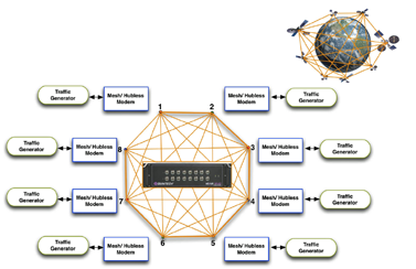
Figure 5a. Full mesh.
The NEXUS matrix switches integrates the splitters, attenuators and switches into a remotely controlled chassis. Figure 5 in the next column shows a) full mesh, b) partial mesh and c) string networks that are rapidly configured using the NEXUS mesh matrix switch.
The NEXUS provides any node to any node connections and allows distance between nodes to be emulated using variable attenuators to adjust the signal levels. The NEXUS matrix is an industry proven non-blocking RF matrix switch that can connect any A port to any B port with independent 0-60 dB variable attenuation per connection.
The addition of a splitter array enables any node to any node connectivity to fully implement the mesh network topology. The NEXUS mesh matrix is an inherently modular design that provides excellent scalability and can be configured to support 8, 16, 32, 64 and 128 nodes. Link parameters such as link path loss and connectivity (on/off) for any node to node can be changed in milliseconds.
Test engineers are able to emulate joining, leaving, grouping and splitting of mesh networks using the NEXUS’ mesh matrix ability to provide real time switching and attenuation of all the radio links individually.
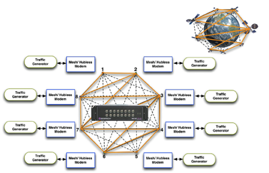
Figure 5b. Partial mesh.
A test engineer or team can use the NEXUS mesh matrix to develop, analyze and verify the upper layer protocols in multiple realistic configurations and test the mesh network’s resilience under dynamic configurations. Performance testing of packet loss, latency and throughput can be measured in greater efficiency and accuracy than by manually changing a patch panel.
Figure 6 is an example of the time saved and the increased number of configurations tested, as achieved by one manufacturer of RF and satellite products through use of the NEXUS mesh matrix.
The top panel in Figure 6 shows how a test of just three network configurations took 8 weeks without using the NEXUS. The bottom panel shows how using the NEXUS setup allowed the engineers to test four times as many configurations while increasing productivity four-fold, resulting in the NEXUS solution enabling a 3 percent savings in schedule. With frequency range spanning 600 to 6000 MHz, the NEXUS mesh matrix can be used for LTE and WiFi for mobile mesh networks and L-band and part of the C-band for satellite spot beam and MF-TDMA mesh and hubless networks.
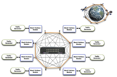
Figure 5c. String.
Saving time and labor, automating accuracy
Engineers require test systems that can be easily configured and controlled to create test scenarios that emulate fee space in a controlled environment. Replacing patch panels with an automated RF switching matrix enables much more rapid and less error-prone re-routing of RF signals. It also offers hot-swappable configurability for multiple tests from a single setup.
In addition to reducing time and difficulty of re-cabling, a suitable RF matrix can reduce the test cycles for many scenarios to a simple routine, easily repeatable operation. RF matrix switches such as Quintech’s NEXUS switch in milliseconds what would take hours with a manual patch panel.
By performing attenuation, addition, and switching on signal paths, the NEXUS can limit the need for external combiners and attenuators, thereby reducing lab costs. In addition, lab engineers and teams can schedule and use a NEXUS system via its Q-LAAMP automation software, allowing multiple overlapping programs or projects to conduct testing more efficiently.
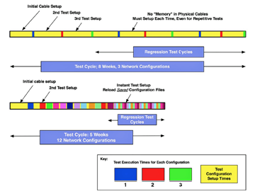
Figure 6. Sample comparison of RF test project saves.
In one successful example, a provider of fighter aircraft avionics and navigation radio systems and vehicle mount military radios needed to validate and certify its new product for compliance with Joint Tactical Radio Systems (JTRS) Software Communications Architecture, and “to leverage its expertise in more than 50 waveforms and functions used on advanced networks and platforms” to create a battlefield communications radio for the US military.
The system needed to support on-the-move communications using a broad range of RF communications technology and missions. By using Quintech’s mesh matrix testing solution, the hardware supplier could rapidly test the mission’s baseline waveforms, such as WNW, SR; cross-banding and channel bandings, as well as future waveforms such as SINCGARS, V/U LOS, UHF SATCOM, and MOUS.
David K. Chan, Ph.D. is the Vice President, Sales and Marketing for Quintech Electronics, Inc., Indiana, Pennsylvania. He holds a B.S. in Applied & Engineering Physics from Cornell University, and a Ph.D. in Materials Science & Engineering from Northwestern University. David has over 23 years of experience in the analysis of materials and test and monitoring of wired, wireless, satellite, and fiber optic analog and digital communications networks.