
X-band is designated by the International Telecommunications Union (ITU) as satellite communications spectrum in the frequency range of 7.25 GHz to 7.75 for space to Earth (receive) and 7.9 GHz to 8.4GHz for Earth to space (transmit).
X-band is used for commercial and military applications because this portion of the RF spectrum provides overall performance advantages that other bands do not, including minimal rain disruption (rain fade), resilience to interference, delivery of data rates approaching that of other less resilient RF spectra, ability to operate with relatively small, remote SATCOM terminals, and acceptance by most developed nations as a spectrum that is reserved for government (and military) use.
Communicating in X-band is robust also has some technical challenges. X-band transmit signals require active filtering and receive signals are vulnerable to unintended active and passive intermodulation (PIM) products, which cause signal degradation and distortion (see discussion below).
In addition, the unusually narrow separation between receive and transmit sub-bands makes X-band inherently vulnerable to the generation of unintended intermodulation products (IMPs) that can lead to interference and disruption.
Propagation Impacts
X-Band is below Ku-Band (12 to 18 GHz) and Ka-Band (26.5 to 40 GHz), so the wavelengths are larger and less susceptible to rain fade and other propagation issues. X-band is able to burn through environmental challenges and enables high link availability, which can be up to 99.9 percent.

Adjacent Satellite Interference
Adjacent satellite interference, or ASI, is a common issue with Ku- and C-band (4 to 8 GHz) communications due to the proximity of Ku- and C-band satellites orbiting in the Clark belt at 2 degrees apart.
Due to this orbital nearness, an inexperienced terminal operator can easily cause interference with poor pointing, poor polarization alignment or signal amplification with a small terminal, as small terminals have wider transmit signals.
X-band satellites are typically placed no less than 4 degrees apart, which lessens the risk of ASI due to pointing or polarization alignment errors. Additionally, X-band signals are filtered, which also lessens the risk of ASI, and terminals require less signal amplification because the X-band spectrum does not require additional help to burn signals through rain and other environmental challenges.
Terminal Size
The size of a terminal — namely, the size of the parabolic reflector — is determined by the data requirement as gain increases as the square of the ratio of wavelength to reflector size. This means gain and data rates increase with reflector size — relative to frequency.
In the U.S., the Federal Communications Commission (FCC) requires C-band terminals to be 2.4 meters or larger, and in Asia and South America, terminals must be at least 1.8 meters to ensure appropriately sized transmit signals.
X-band terminals can be quite small as compared to C-band terminals, yet possess impressive gain. For example, the X-band transmit gain for an AvL 1.2 meter Model 1050 flyaway antenna is 38.1 dBi, whereas the gain for an AvL 1.6 meter Model 1220 antenna is 40.5 dBi and the gain for an AvL 2.0 meter Model 2020 antenna is 42.8 dBi.
Transmit Signal Filtering
As X-band receive (7.25 to 7.75 GHz) is only separated by 150 MHz from X-band transmit (7.9 to 8.4GHz), X-band communications require the use of filters to separate the signals and keep them from becoming intermingled and generating unintended IMPs.
By comparison, Ku-band receive (11.7 to 12.7 GHz) is separated by 1.3 GHz from Ku-band transmit (14 to 14.5 GHz), meaning Ku-band is far less susceptible to generating unintended IMPs.
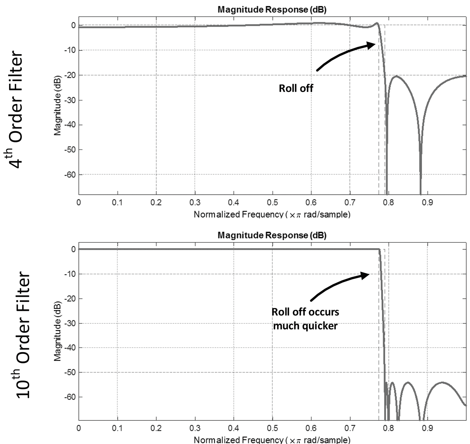
As an X-band filter’s performance over changing frequency goes from pass band to stopband, the rate at which the insertion loss changes from minimal attenuation to heavy attenuation is known as the “roll off.” Because the frequency separation between transmit and receive occurs relatively quickly at X-band, it is important to pay more attention to the level of isolation in comparison to Ku-band.
Typically speaking, higher order filters are used to increase the rate of roll off. The tradeoff is that the higher the order of the filter, typically the filter must become physically larger.
As illustrated, the roll off increases as the order of the filter is increased.
Passive and Active Intermodulation
There are two types of IMPs: active and passive.
Active IMPs are generated through an active component, such as the transmit amplifier — the problematic IMPs can be filtered and rejected within the amplifier using established filter design techniques.
Passive IMPs (PIMs) are typically the most troublesome, as they can they appear as the sum or the difference of the two original signal frequencies. They also may add in a manner where either or both of the original frequencies are multiplied by an integer.
Typically, however, as the order of these integers increases, the amplitude of the product decreases. Nonetheless, as the number of channels increases, the number of possible intermodulation products increases quite rapidly, ultimately making systems with an increased number of channels more susceptible to passive intermodulation.
PIM Generation
The foundation of PIM effects is the use of two distinct frequencies in the antenna, whereby a non-linear passive component is excited by both frequencies simultaneously.

When the intermodulation interference products are generated by the nonlinear materials in the passive components, they appear as the sum or the difference of the two original signal frequencies.
They also may add in a manner where either, or both, of the original frequencies are multiplied by an integer as well. Typically, however, as the order of these integers increases, the amplitude of the product decreases.
Nonetheless, as the number of channels increases, the number of possible intermodulation products increases rapidly, ultimately making systems with an increased number of channels more susceptible to passive intermodulation.
Material selection for PIM mitigation is critical. Metals to avoid on antenna components include ferromagnetic metals such as ferrites, nickels and steels, including some types of stainless steel.
These materials exhibit hysteresis when exposed electromagnetic phenomenon, resulting in PIM products. Metals that oxidize quickly or produce significant amounts of rust also should be avoided.
PIM detection and measurement can be challenging. PIM products are typically low level compared to signals intended for data transmission. However, due to the fact that transmitters share many of the same transmission lines as the receiver (as parts of the antenna and feed system), even low level PIM products can cause significant problems.
PIM is a reality of RF systems that directly threatens operational readiness for military communications, as soldiers rely heavily on a constant flow of information. Though this effect can be subtle, soldiers in theater are often in harsh environments — hot and sandy or damp and salty — that can create or hasten PIM-inducing issues on an antenna. As such, many U.S. military communications programs specify that antennas must be designed and produced as “Low PIM” in an attempt to mitigate the issue altogether.
Spread Spectrum
Spread spectrum techniques are often used with X-band military communications to enable greater resistance to jamming and signal interception.
Spreading bandwidth within a frequency also greatly increases satellite bandwidth requirements (higher user cost) but reduces the likelihood of ASI, thereby enabling the more efficient use of the bandwidth.
Spreading the spectrum enables a channel to be broken (or spread) across multiple pieces across the full band. If, for example, a signal is spread across six channels instead of two, and one channel is jammed, the remaining five will maintain the communications link. This ability to communicate with a lower risk of jamming and intercept is a high priority for the U.S. DoD.
Impressive Performance
Communicating in X-band is versatile and robust and this is why it’s in demand for commercial and military communications.
Additionally, technical challenges aside, X-band enables impressive performance advantages that other bands do not offer and they include minimal rain disruption (rain fade), resilience to interference, delivery of data rates approaching that of other less resilient RF spectra, and the ability to operate with relatively small, remote SATCOM terminals.
www.avltech.com

Krystal Dredge is the Director of Marketing for AvL Technologies. Krystal has 15+ years of product marketing experience in satellite and wireless communications, and most recently worked at Honeywell and EMS Defense & Space Systems in Atlanta prior to joining AvL in 2012. She holds a BSJ degree in Journalism from the University of Kansas and an MBA from Wichita State University.
Ian Timmins, Ph.D., is the Principal RF Engineer at AvL Technologies. Prior to joining AvL, Ian was VP of Engineering for Optical Cable Corporation’s Enterprise and Harsh Environment lines of business. He also previously held technical roles with Dell Computer Corporation, Cisco Systems and COM DEV Space Group. Ian holds a Ph.D. in Electrical Engineering and is an adjunct professor with Western Carolina University.
AvL Technologies is an engineering centric OEM specializing in transportable satellite antennas and positioner systems. With experience in designing X-band components and mitigating passive intermodulation, AvL offers a wide variety of X-band SATCOM products for both commercial and government applications.