
Subject: Antenna Technologies for Next-Gen COTM: Requirements and Solutions
William (Bill) Milroy currently serves as Chairman and CTO of ThinKom Solutions, Inc., located in Hawthorne, California, and is focused on the design, development, and manufacture of innovative antenna access solutions for the Fixed and Mobile Broadband Wireless Communication markets.
Prior to co-founding ThinKom, Mr. Milroy held the position of Senior Engineering Fellow within the Electromagnetic Systems Department of Raytheon’s Electronic Systems (ES) Segment. During his tenure at Raytheon (Hughes Aircraft), Mr. Milroy managed and led the RF antenna design, development, and manufacture of a wide range of antenna array implementations and products for radar and communication applications in both the commercial and military marketplaces including 1-D and 2-D Electronically-Scanned Arrays (ESA’s).
He is the author or co-author of nine journal and symposia papers in the fields of Network Analysis, Circuits, Antennas, and Microwaves. He is the inventor or co-inventor of more than 40 awarded and pending patents in the fields of Electromagnetic Scattering, Materials, Microwave Devices, and Antennas. Mr. Milroy is a past Chairman of the Los Angeles Chapter of the IEEE Antennas and Propagation Society (APS), and a Guest Lecturer at the UCLA Anderson School of Business Management. He is a past Technical Reviewer for both the National Science Foundation (NSF) and the IEEE APS Transactions Journal.
Note: The U.S. Army is looking to upgrade its Communications On-the-Move (COTM) capabilities. This will require satellite antenna designs that support the new emerging requirements. To learn more about this issue, Bill Milroy offers his expertise regarding mobile SATCOM antenna technologies.
First, Mr. Milroy, please give our readers a brief snapshot of ThinKom and its experience in mobile SATCOM antennas.

Bill Milroy
Sure. ThinKom Solutions is a privately held company that was founded in 2000 to design, develop and bring to market next-generation satellite communication antennas. Currently we have more than 130 employees at our 75,000 sq. ft headquarters and manufacturing/testing facility in Hawthorne, California.
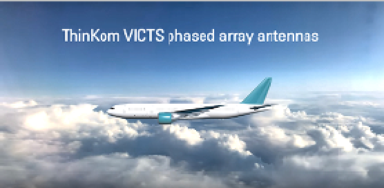
Our primary core technology is our patented VICTS (Variable-Inclination Continuous Transverse Stub) antenna architecture. ThinKom is probably best known as one of the largest suppliers of Ku-band and — more recently — Ka-band antennas for commercial aviation in-flight connectivity (IFC). Our low-profile phased-array antennas are active on more than 1,550 aircraft with a track record of over 21 million accrued flight hours.
That being said, from the beginning we have also been deeply involved in government and military aero, land and maritime SATCOM programs. For example, in 2018, ThinKom was competitively selected to supply Ka- band fuselage-mounted antennas for the E4B National Airborne Operations Center aircraft. We are currently working under contracts with General Dynamics to test our COTS VICTS antennas for COTM in U.S. Army armored brigades and with the Defense Innovation Unit (DIU) to test and evaluate our COTS Ka-band antennas to support Multi-Domain Tactical Communications (MDTC) for U.S. Navy warships.
Last year we achieved an important milestone when we completed successful over-the-air tests with our COTS VICTS antenna on the frequency-hopping waveform of the AEHF protected communications satellite network.
Tell us a little more about the pilot program with General Dynamics for the U.S. Army armored brigades.
Bill Milroy
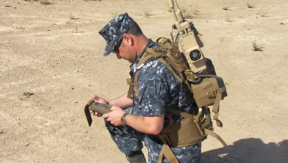
We recently delivered three of our ThinSat® 300 vehicular satellite antennas to General Dynamics Mission Systems under a pilot program evaluating COTM options for command post vehicles in armored formations in U.S. Army Armored Brigade Combat Teams (ABCT). The goal is to enhance mobile battlefield network communications, mission command, situational awareness and ultimately unit lethality. The Army will conduct an ABCT COTM pilot this year to evaluate the ThinKom COTS antennas integrated onto select vehicles. The ABCT COTM experimentation program is expected to lead to prototype deployment and testing under the Army’s two- year Capability Set cycle in 2023.
Our field-proven TRL 9 COTS antenna technology — delivering the equivalent performance of a 50 to 75 cm parabolic dish in a compact, low-profile, 10 cm form- factor — uniquely provides a highly reliable and rugged phased-array solution.
Would you please summarize what you see as the current and near-term military requirements for COTM SATCOM antennas?
Bill Milroy
The current legacy system requirements for tactical OTM SATCOM over GEO satellites call for agile, single-beam, single-band, (Ku- or Ka-) systems, with low Size, Weight, Power and Cost (SWaP-C). Desired attributes include a 75 cm or smaller vehicle footprint, a weight of 100 pounds or less and a maximum prime power requirement of 650W, with G/T and EIRP performance equivalent to a 45 cm to 75 cm parabolic dish, but in a low-profile form factor of 20 cm or less in height. As we look to the near- term future, we understand that the U.S. Army seeks to steadily move toward higher throughput terminals that can support both GEO and newer and evolving LEO satellite constellations, while taking care not to sacrifice the low SWaP-C characteristics that are key to broad adoption.
Looking further into the future, what are the requirements that will govern next- generation COTM SATCOM for military applications in terms of form-factor and performance characteristics?
Bill Milroy
In terms of “next-gen” COTM, we foresee the need to support multiple beams for simultaneous or make-before- break operation via two or more compact conformal arrays situated in different placements on a given vehicle. This “location diversity” serves to mitigate or even eliminate traditional vehicle turret and related blockage issues. It will also support battlefield damage redundancy and survivability, enhance low-elevation performance and provide superior mitigation of terrestrial blockage from trees, structures and terrain — particularly important in true COTM operation.
Support of wider channel bandwidths (250 to 2,000 MHz, depending on application) will also be mandatory in order to accommodate evolving, jam-resistant, spread- spectrum and frequency-hopped waveforms. The challenge, of course, is to enable and bring forth these added next-gen capabilities while conforming to aggressive SWaP-C constraints — we are confident we are up to the task.
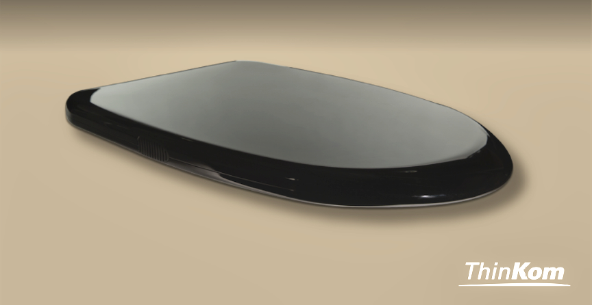
Photo of ThinKom’s ThinSat™ 300 vehicular satellite antenna,
courtesy of the company.
Do you foresee a requirement for flat panels mounted under the skin of the vehicle?
Bill Milroy
This certainly would be desirable from the point of view of low visual and radar signatures, as well as overall operational robustness and survivability.
Flat-panel phased-array terminals, such as VICTS or electronically scanned arrays (ESAs) have, by nature, the low-profile characteristics that would permit integration onto — or even into — the skin of the vehicle with custom modifications. However, area footprint, profile and prime power are also key considerations. As compared to a VICTS array, a typical ESA-based terminal would have to be 3x to 8x larger in area to realize the equivalent gain and G/T performance and would require 4x to 8x the prime power to operate.
Mechanical form-factor and ruggedness are essential in fielded terminal systems, but electronic survivability has taken on increased importance over the past few years.
Specifically, broad adoption of vehicle-mounted Joint Counter Radio-Controlled Improvised Explosive Device (RCIED) Electronic Warfare (JCREW) Counter- IED and similar high-power RF systems, as well as the more traditional EW/EA susceptibility concerns, have placed increased emphasis on terminal EMI/EMC susceptibility/ survivability per MIL-STD-461 and similar standards.
Based on their integrated shielded electronics and unique passive RF features, ThinKom’s VICTS-based antennas are unusually robust and survivable in today’s and tomorrow’s battlefield EMI/EMC environments.
JCREW IED use in the field. Photo is courtesy
of Northrop Grumman.
You mentioned Protected Comms earlier. How will this affect SATCOM COTM antenna requirements?
Bill Milroy
The unusually wide-channel instantaneous bandwidth supported by ThinKom’s VICTS phased arrays are ideally suited for hosting and supporting advanced LPD/LPI/ AJ (TRANSEC) waveforms, including DSSS and hopped- based variants for protected tactical waveform (PTW). Our K/Q-band variant was recently OTA tested on the AEHF constellation, supporting the full-range of available modes, data rates and communication plans.
Waveform compatibility is recognized as key to TRANSEC operations and overall satellite constellation interoperability. However, of equal importance are the overall RF sidelobe and RF/EMC emission characteristics of the antenna and terminal. MIL-STD-188-164B specifies stringent requirements with respect to these attributes, and ThinKom’s VICTS-based systems have already been approved for fielded operation under this standard.
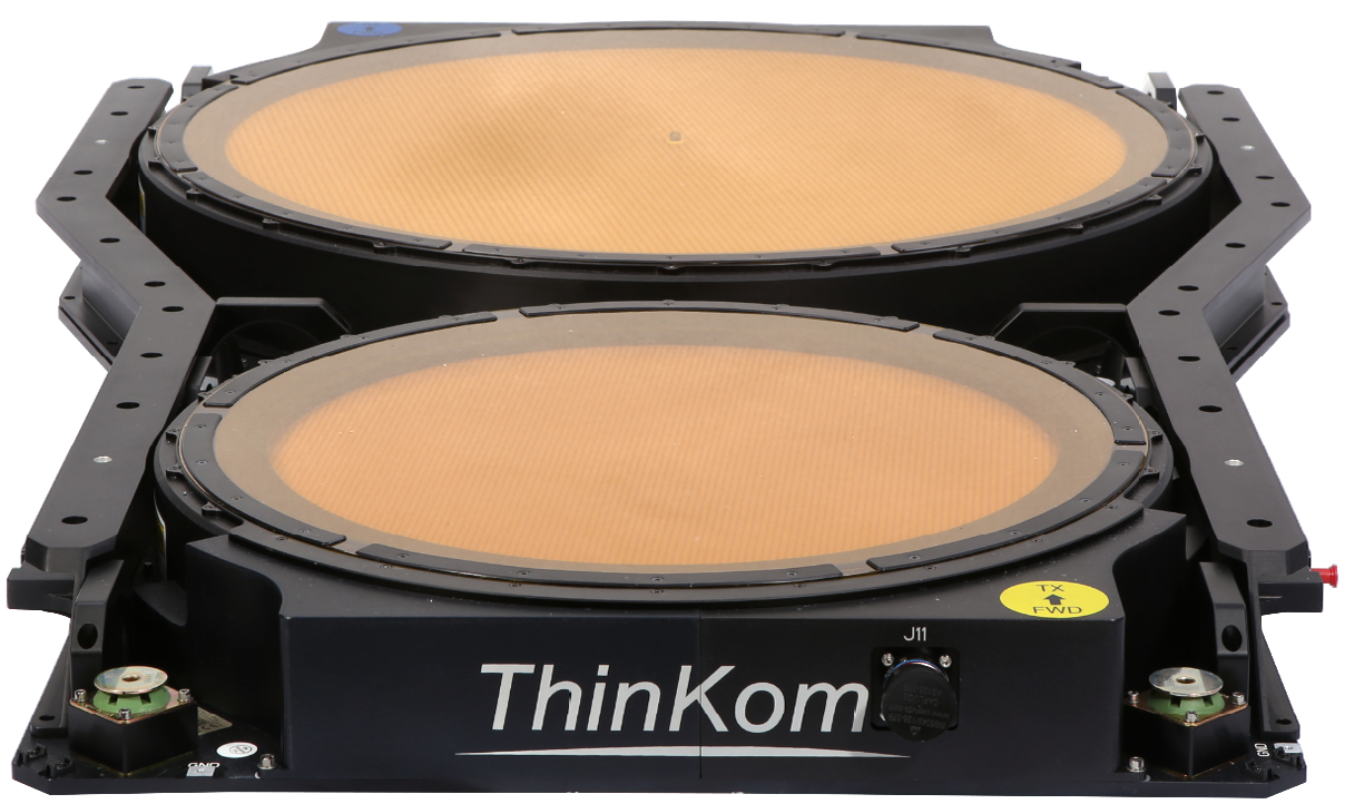
ThinKom ThinAir 2517 antenna, without radome.
Photo is courtesy of the company.
Do you foresee a requirement for multi- frequency antennas?
Bill Milroy
This would present serious SWaP-C and operational challenges. If multi-frequency (X-, Ku- and/or Ka-), the terminal would need to be burdened with 2x to 3x the RF components, such as the BUC and LNB, as well as feed chains in the case of traditional parabolic dish terminals. This will increase SWaP-C and will decrease reliability especially in austere and rugged environments.
Staying within one common frequency band (Ku- or Ka), but allowing for multi-constellation (GEO, MEO or LEO) use, reduces the overall SWaP-C demand while providing the full multi-constellation redundancy, flexibility and resiliency that users are looking for.
We read and hear a lot these days about electronic scanned arrays (ESAs). What are their advantages and limitations for the COTM battlefield environment?
Bill Milroy
First, let me point out that there are different types of ESAs. Those that are true time delay (TTD) based could, theoretically, support larger IBWs. However, for most ESA designs, the beam position undesirably moves as a function of frequency. If the beam moves too much over a given channel bandwidth, then part of that bandwidth will be “lost” (missed), or alternatively, at least some of the bandwidth will experience a profound roll-off loss at the extremes of the frequency band.
Of course, instantaneous channel bandwidth is just one of the key considerations. As I mentioned previously, size and prime power are both in short supply on most COTM vehicles and platforms and the fundamental limitations of ESAs in regard to both of these metrics may ultimately limit their viability for many applications.
How does VICTS differ from ESAs?
Bill Milroy
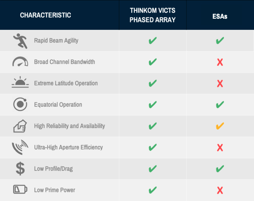
The table above lists the key SATCOM phased-array considerations and metrics, comparing the attributes of a VICTS-based terminal to those of a typical ESA-based variant. The standard VICTS antenna has a single, quasi-optically scanned beam that reliably supports wide channel bandwidths and with area/gain efficiencies that are 2x to 8x that of a typical ESA.
If multi-beam is required for the antenna system, multiple VICTS apertures can be used in the antenna system, with a footprint that is still significantly smaller than that of an ESA with prime power and thermal dissipation an order of magnitude lower.

Similarly, if multiple frequency bands are truly required of a given antenna-terminal application (which would be an uncommon need) multiple apertures operating in different frequency bands can be employed, with the multi-band VICTS-based terminal again presenting an overall footprint smaller than a multi-band ESA.